


 by Tom Gurney
Tom Gurney BSc (Hons) is an art history expert with over 20 years experience
Email: tomgurney1@gmail.com / Phone: +44 7429 011000
A skeleton is a system, not a style
A steel frame is an assembly, not simply a material. Columns and beams can release a façade from carrying the floors above, but their usefulness depends on joints, foundations, floors and the means of resisting sideways movement. Glass, brick, concrete, timber and protective finishes remain part of the building. Even a structure whose metalwork seems entirely visible may conceal important work in its floors, connections or coatings. [1], [9], [10], [11], [19], [22], [27]
Steel-frame architecture consequently extends well beyond the skyscraper. It includes warehouses with repeated portal frames, schools whose roofs span column-free teaching halls, museums with carefully controlled enclosures, prefabricated verandas and light walls made from folded sheet. These buildings share possibilities of manufactured components and relatively slender support, but they do not share one inevitable appearance or one system of construction. Their histories bring together industrial production, skilled labour, commercial pressures, environmental control and changing occupation. [11], [19], [22], [24], [28], [29]
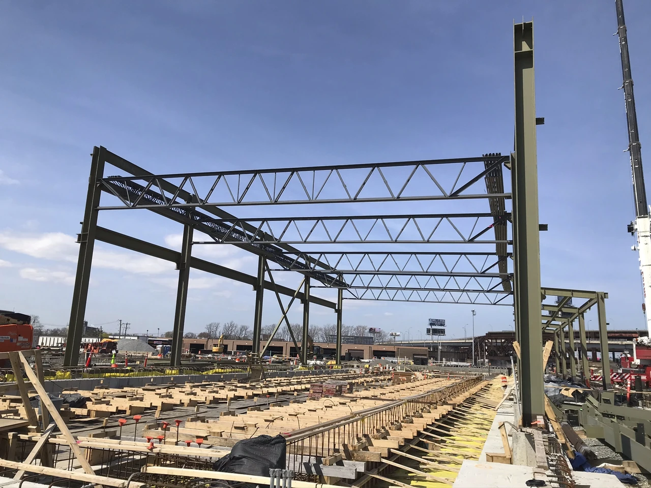
At a Glance
- DefinitionA connected framework of steel members, distinguished from its enclosing walls and from other participating structural systems. [1], [19], [22]
- MembersRolled profiles, fabricated girders, hollow sections, trusses, cast-steel nodes and folded-sheet framing serve different roles. [11], [19], [22], [24], [29]
- LoadsGravity support works alongside bracing, joint restraint, cores and floor action that resist lateral movement. [3], [4], [19], [24], [27]
- ConnectionsRivets, bolts, welds and screws belong to different manufacturing and assembly practices. [7], [9], [11], [19], [24], [29]
- Early developmentNineteenth-century masonry, cast iron, wrought iron and steel overlapped rather than changing in a single invention. [1], [2], [3], [4], [9]
- EnclosureA curtain wall can be separate from the principal frame; visible metal is not necessarily primary support. [10], [19]
- SpaceSpans, repeated bays and thinner enclosures can improve daylight and useful area, while services and use still constrain layouts. [3], [4], [11], [22], [28]
- ProtectionNon-combustible steel still changes under heat and requires assembly-specific protection and assessment. [27]
- ConservationCorrosion, moisture, thermal movement, altered loads and historic finishes require attention together. [13], [15], [17], [24]
- ReuseKeeping a frame, moving it, recovering members and recycling scrap are different actions with different practical consequences. [28], [35]
Contents
- Reading a frame: members, joints and load paths
- Making steel into architectural members
- Early skyscrapers: a transition, not a single first
- Monadnock: steel within a masonry landmark
- Wainwright: protection, rental space and terracotta
- Crown Hall: a roof that frees a teaching room
- Seagram: the steel frame and its bronze image
- Neue Nationalgalerie: an apparently flat roof
- Centre Pompidou: the connection becomes architecture
- Sendai Mediatheque: tubes, floors and services
- Prefabricated steel in Congo: factories and colonial networks
- A mixed frame's changing life at Mbanza-Ngungu
- Fire, moisture and the protected frame
- Ordinary halls and the possibilities of reuse
- Designing a second life: floors, information and trade-offs
- Workers and the image of the frame
- Selected chronology
Reading a frame: members, joints and load paths
The simplest skeletal picture consists of vertical columns and horizontal beams. Floors deliver their loads to beams; beams pass them to columns; foundations transmit them into the ground. When this framework carries the principal floor loads, the outer wall need not accumulate the weight of every storey above. A thinner enclosure becomes possible, with larger openings and different relationships between inside and outside. The separation is an architectural opportunity, not a description of every metal-framed building that has ever been built. [1], [3], [9], [19]
Gravity is only one part of the problem. Wind or earthquake action requires a route through the structure to its supports. Diagonal braces and ties, sufficiently restrained connections, participating walls or cores, and the action of floors can contribute in different combinations. A building may therefore have steel columns for gravity support but a substantial concrete or masonry element for lateral stability. Removing an apparently secondary wall can change more than the room's appearance. [3], [4], [19], [24], [26], [27]
Masonry between steel members can affect that response even where it is not described as the principal structure. James Potterton's 2009 Cal Poly study examined prototype frames with unreinforced masonry infill through nonlinear static modelling in seventeen city settings. Its university abstract identifies damage and yielding as part of that investigation. The research raises a useful architectural question: how does an enclosing wall participate when the frame moves? Treating every panel as a passive screen can obscure the interaction between enclosure and support. [26]

Text alternative for the diagram
Frame, enclosure and stability perform different work. Original conceptual sketch; braces illustrate one possibility, not the complete design of a particular building.
- Frame, enclosure and load routes
- Conceptual — not measured
- Gravity route
- Floors → beams → columns → foundations.
- Lateral route
- Braces are one possible route; cores and joints can also participate.
- Enclosure
- Walls may enclose without carrying floors. Hybrids need their own reading.
The Centre Pompidou makes some of those distinctions conspicuous. Long spanning beams, columns, external ties and cast-steel gerberettes cooperate in supporting the floors, while enormous façade crosses and horizontal bracing address stability. In the prefabricated hotel studied at Mbanza-Ngungu in the Democratic Republic of Congo, by contrast, a central masonry and concrete system participates substantially in support and stability. Both contain steel frames; neither is adequately understood as isolated steel sticks surrounding an empty volume. [19], [20], [24]
Connections make the separate members behave as an assembly. A joint represented as a pin in an analytical drawing permits a different relationship from a fully restrained one. Real details can fall between those simplifications. Web angles, contact surfaces, fasteners and adjoining members affect rotational restraint. The 2026 study of the Congolese hotel identified three different floor-joint arrangements; treating their behaviour identically would have concealed a meaningful difference in the building. [24]
More realistic joint behaviour does not automatically make a deficient frame adequate. In that study, incorporating the semi-rigidity of one connection type reduced calculated beam utilisation and deflection, but did not remove the problems in the particular ground-floor members. The distinction between a better model and a satisfactory result is important: a steel frame's reputation for adaptability cannot substitute for understanding its actual connections, condition and loads. [24]
Making steel into architectural members
Steel can reach a building in several forms. An I- or H-shaped profile organises metal into a web and flanges rather than a solid rectangle. Fabricated girders assemble plates and other pieces into larger members; trusses distribute work through a network; hollow sections offer another range of shapes. The four great exterior bents at Crown Hall, the tubular trusses at Sendai Mediatheque and the cast-steel nodes at the Centre Pompidou demonstrate how differently a designer can turn steel into a frame. [11], [19], [22], [24], [35]
Casting and steel are not opposites. Pompidou's gerberettes are cast steel, not the grey cast iron associated with many nineteenth-century columns and ornamental façades. Its hollow columns were also manufactured as cast-steel components and delivered in sections for welding on site. The material's name, its manufacturing process and its structural function must be distinguished. A cast node joining other members belongs to a different architectural system from an old cast-iron column, even when the word cast appears in both descriptions. [19], [21]
Cold-formed framing represents another distinction. Manufacturers feed sheet steel through a series of dies or rollers that progressively bend it at ambient temperature, without adding heat for that shaping operation. C-shaped studs, tracks, joists and U-, Z- or hat-shaped profiles differ from the heavier structural shapes produced through hot-rolling processes. Folded edges and returning lips help give thin members their form and stiffness; the web, flange and lip are parts of a designed profile, not incidental folds. [29]
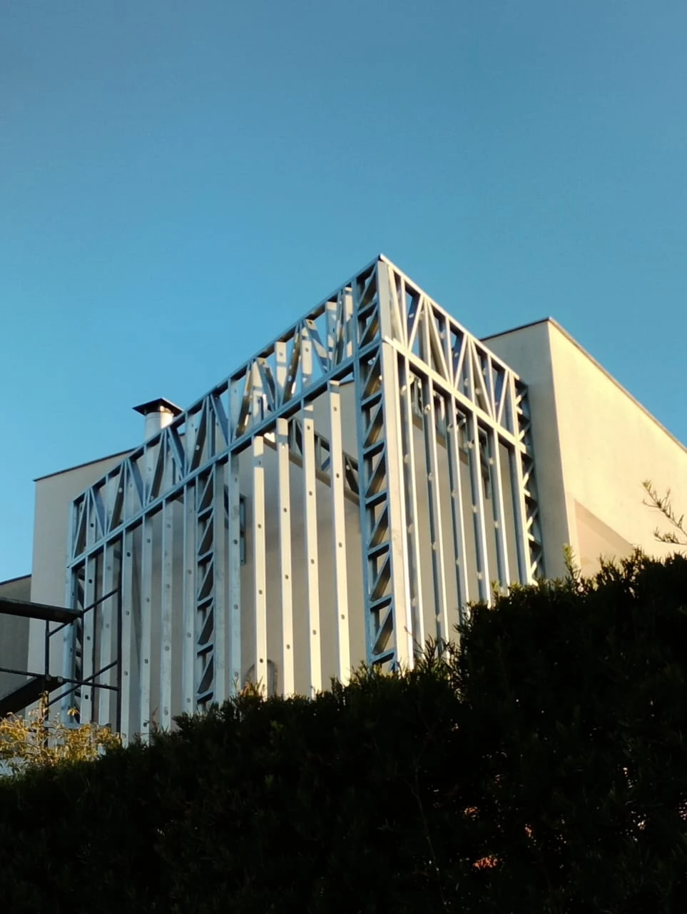
These light members can serve non-load-bearing interior partitions, but they can also belong to designed structural wall, roof and floor systems. Their role cannot be decided by appearance alone. A bank of metal studs exposed during refurbishment may be a fit-out inside an entirely different principal structure. Conversely, a low- or mid-rise building may depend on a light steel system throughout. Screwed connections and closely repeated members bring a different scale of assembly from a museum's huge welded roof or a cast-steel node. [29]

Text alternative for the diagram
Rolled or fabricated members, cast-steel nodes and cold-formed profiles belong to different production practices. Original silhouettes, not proprietary sections or measured connection designs.
- Forming a member is not naming a material
- Conceptual — not measured
- Profile / girder
- Rolled profiles and fabricated members organise steel into useful shapes.
- Cast-steel node
- Casting names a process. A steel node is not historic grey cast iron.
- Folded sheet
- Thin sheet forms webs, flanges and returning lips at ambient temperature.
The folded-sheet system also has an environmental history. Coated coil and protective finishes help address exposure, but a coating is not a promise of immunity to every form of moisture or damage. Nor does the steel's inability to supply fuel establish the fire resistance of the occupied wall or floor around it. Its performance belongs to the whole assembly, including its linings, interfaces and protection. [27], [29]
Factory preparation can divide work between places without eliminating skill. In the Belgian Grandes Chaudronneries de l'Escaut (GCE) prefabricated system, angle cleats were riveted in the shop and the frame was bolted together after transport. Trial assembly checked the components before export. At Crown Hall, field-welded visible joints were finished to give the external metalwork a continuous appearance. Pompidou needed specialised fabrication, large components and carefully organised delivery through Paris. A clean finished line can therefore embody a great deal of fitting, coordination and site work. [11], [19], [24]
| Member or assembly | What distinguishes it | What its appearance does not establish |
|---|---|---|
| Rolled steel profile | A manufactured beam or column section used within a connected system. [24], [29] | The composition or condition of every neighbouring historic member. [24] |
| Fabricated girder or bent | Several components form a larger spanning or supporting element. [11], [35] | That all its joints disappear or every surface remains unprotected. [11], [27] |
| Tubular steel truss | Hollow members cooperate through a lattice, as in Sendai's principal shafts. [22] | That every tube has the same purpose or contains identical services. [22] |
| Cast-steel node | Steel is moulded into a joining component, as with Pompidou's gerberettes. [19] | That it is nineteenth-century grey cast iron. [19], [21] |
| Cold-formed stud and track | Thin sheet is progressively shaped into profiles without added heat. [29] | Whether the visible wall is structural or nonstructural. [29] |
| Composite steel–concrete floor | Shear connections allow beam and slab to cooperate. [35] | That normal frame bolts make the slab readily demountable. [35] |
Early skyscrapers: a transition, not a single first
Chicago's Home Insurance Building is important because it belongs to a changing practice, not because one label resolves every question about its fabric. William Le Baron Jenney's building opened in 1885 with ten storeys and was demolished in 1931. Chicago Architecture Center's accounts foreground its skeletal construction, enlarged windows and place in the development of the skyscraper, but describe its materials and walls differently: one acknowledges bearing masonry, while another emphasises cast-iron support and nonstructural stone sheathing. It is better understood as an influential transitional case than as an uncomplicated first pure-steel frame. [1], [2]
The commercial setting mattered. Population growth, concentrated corporate activity and rebuilding after the Great Chicago Fire encouraged new forms of urban accommodation. Thinner enclosures and larger windows made upper floors more attractive and usable. Yet metal did not act alone. Occupation, access, investment, services, foundations and regulation all helped turn a structural possibility into a rentable building. Chicago's later Reliance Building, described by the Architecture Center as a major early skeletal example completed in 1895, makes the relationship between frame and expansive glazing particularly apparent. [1], [2]
New York's Tower Building gives the economic problem a compact form. Bradford Lee Gilbert's eleven-storey building of 1889 stood on a Broadway frontage only 21.5 feet wide. Thick supporting walls would have consumed a significant share of such a narrow site. The metal cage's value lay not only in height, but in preserving usable area and admitting larger windows. The Tower Building was demolished in 1914, leaving accounts and images to explain its place in this transition. [3]
Its structure was hybrid. In the Skyscraper Museum's account, drawing on engineer Donald Friedman's explanation, wrought-iron beams and cast-iron columns formed the lower seven-storey skeleton. Above it sat four storeys combining steel framing with bearing walls. The upper masonry imposed weight on the cast columns below, whose behaviour in compression differed from their limitations in tension. This is a specific historical arrangement, not a recommendation that masonry weight universally improves a frame. [3]
Official recognition followed practice. New York's building code did not expressly permit skeleton-frame construction until 1892, but the Department of Buildings had approved Gilbert's individual application. The sequence distinguishes a particular permission from a later general provision. Technology, official judgement and established rules did not necessarily move together. Treating the date of a code change as the invention of a construction method would miss that negotiated history. [3]
These early buildings also challenge the idea that iron, steel and masonry occupied separate consecutive eras. Cast columns, wrought beams, newer steel members and thick walls could coexist in one building. The frame's history is partly the history of deciding which material should do which work, and of extending an accepted practice into unfamiliar applications. The most revealing question is often not which building won a first, but how its particular combination changed architectural space. [1], [2], [3], [4]
Monadnock: steel within a masonry landmark
The northern Monadnock in Chicago is commonly remembered for its thick bearing-brick walls. Those walls are real, but they do not describe the whole structural story. Thomas Leslie's study for the Canadian Centre for Architecture follows the drawings to reveal metal columns, steel lateral ties and bracing, and the support of projecting bay windows. The masonry and metal worked together. Calling it a masonry skyscraper should not make the steel disappear. [4]
The design changed substantially between the early proposals and construction around 1890–91. Carefully developed cast-iron details from 1885 belong to an earlier phase. Later drawings show different possibilities in steel and in its connections to masonry. Those phases are not interchangeable evidence: a drawing of a proposed casting does not establish the material of every final column. The CCA's archive contains conceptual, design-development, working, construction and service drawings, including tenant-related interiors and structural calculations, across a long sequence of decisions. [4], [5], [6], [7]
Lateral resistance was one of those decisions. In Leslie's account, steel bracing and diagonal ties connected parts of the exterior masonry and internal structure. The capacity to work in tension and to form effective connections made steel useful without requiring the building to abandon bearing brick. A heavy-looking exterior could therefore participate in a more complicated metal-and-masonry system than its famous silhouette suggests. [4]
The projecting bays are especially instructive. They improved light and ventilation and added useful, rentable area, while their undulating exterior continued the architectural language of the masonry wall. Cantilevered steel members supported the projected floors and enclosure. Structural capability and outward appearance were not identical: steel helped produce an apparently sculpted brick form rather than necessarily advertising itself on the street. [4], [8]
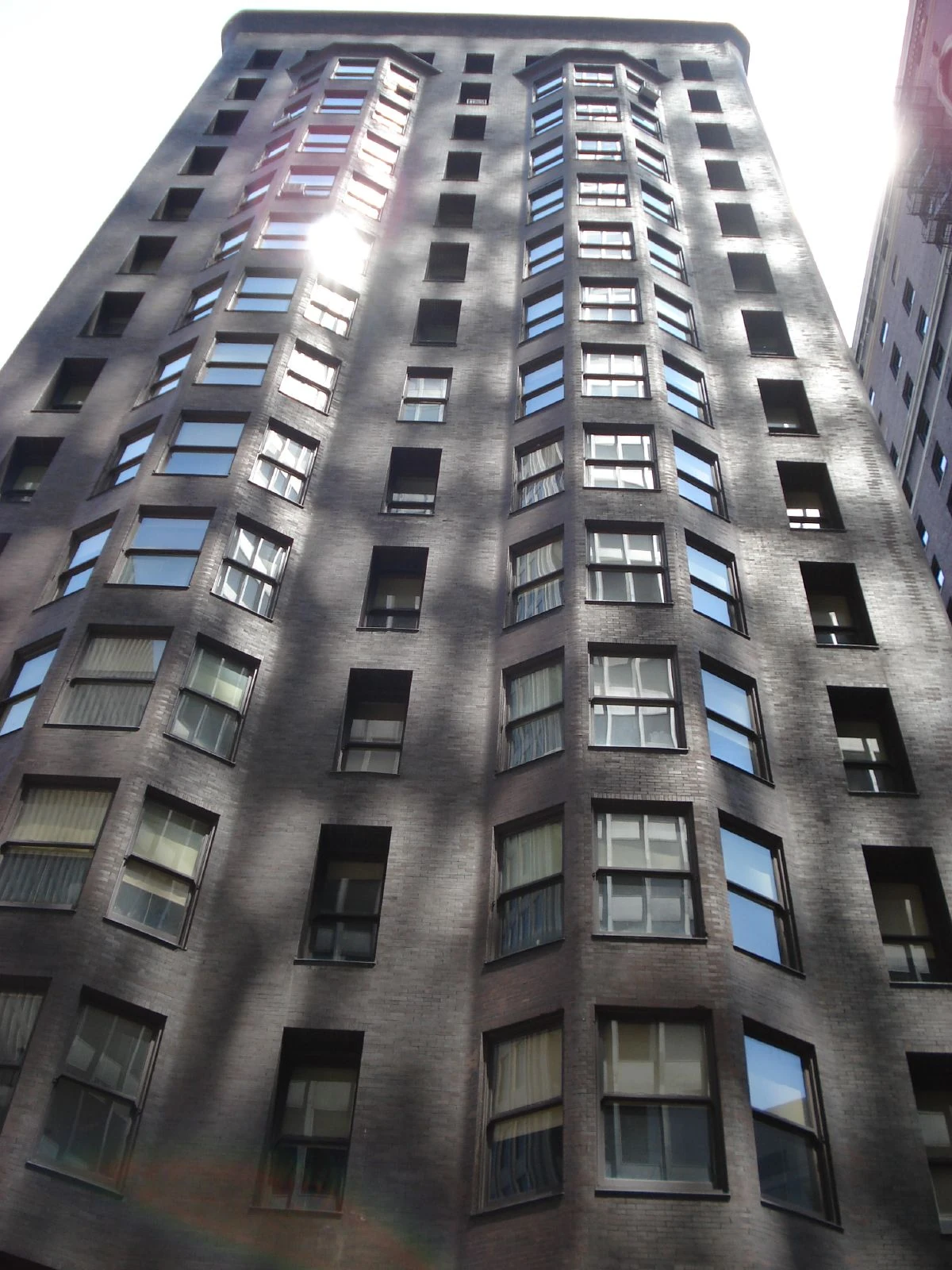
Leslie also reads the drawings as evidence of commercial pressure. The later sheets contain hurried additions and leave some details to the constructor, while changes in the Brooks brothers' investment affected the scheme. This is the scholar's interpretation of the archive, rather than a transparent record of every designer's motive. Nevertheless, it usefully places the frame within a property market, a programme and a division of professional responsibility. [4]
The southern part, designed by Holabird & Roche in 1891–92, used a skeletal system that allowed a different treatment of the ground-floor openings and retail light. The contrast is not a simple contest in which one half is backward and the other modern. It shows neighbouring answers to support, rentable space and architectural expression. The whole block preserves the coexistence of solutions, not a clean boundary between a masonry age and a steel age. [4]
The drawings themselves are designed objects. Burnham & Root's early cast-column sheet arranges elevations, plans and sections to explain several connections; a later blueprint credits the Keystone Bridge Company and describes proposed beam-to-column details. A pale graphite study records bay-window brackets and notes on steel framing. Their media, inscriptions, manufacture and project stage locate them within the practical making of architecture. They also make a different kind of image from a photograph of the finished street front. [6], [7], [8]
Wainwright: protection, rental space and terracotta
Adler & Sullivan's Wainwright Building in St Louis, built in 1890–91, brings the steel skeleton together with an emphatically modelled façade. The historical nomination describes a ten-storey riveted and braced steel structure, protective tile and shelf angles supporting the enclosure. It also uses the broader language of iron and steel. The useful lesson is the coordinated assembly, not a claim that the building establishes a universally accepted pure-material first. [9]
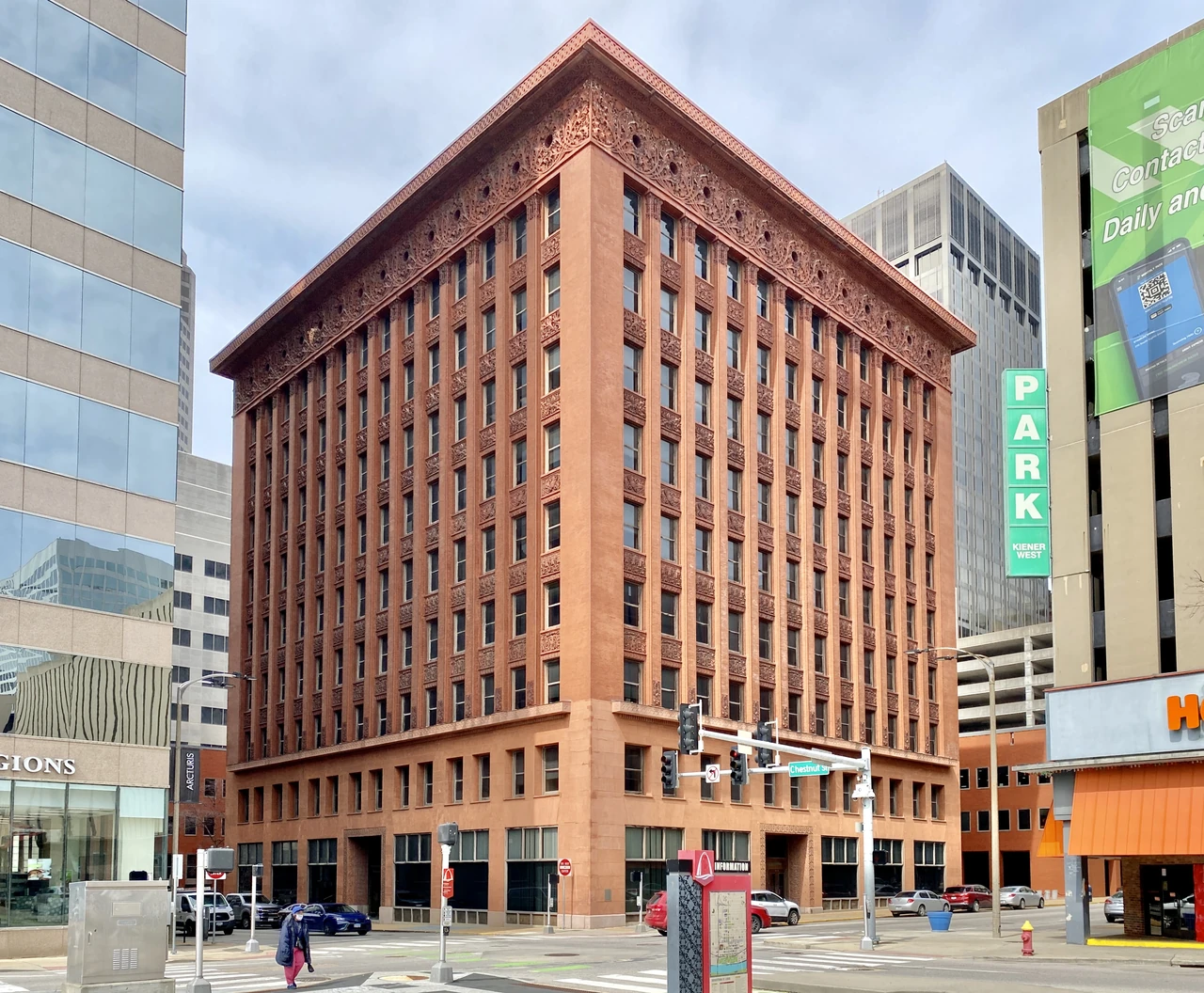
Its U-shaped plan brought light into the offices, while four lifts and stairs made the upper rental floors usable. Leasing drawings from 1891 show rooms, partitions and the commercial organisation of space. These plans describe occupation rather than functioning as complete structural calculations, but they clarify why a skeleton mattered to the building's owners and tenants. Support was valuable because it helped accommodate people and businesses in a particular urban arrangement. [9]
Sullivan did not simply draw every structural member on the façade. Some of the apparent piers emphasise verticality without corresponding to principal frame columns. Terracotta foliage, the hierarchy of storeys and the crowning cornice produce a composition with its own visual force. The expression of a tall office building is therefore neither an exact diagram of concealed steel nor unrelated decoration placed on a neutral cage. [9]
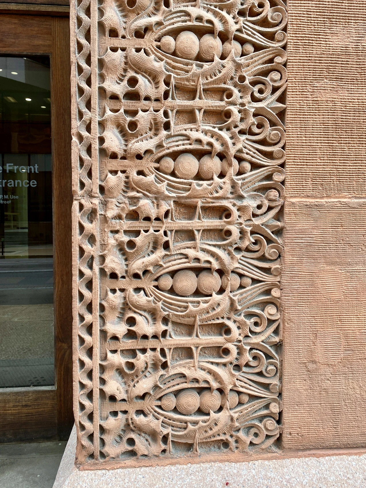
Tile encasement and the adjoining floor and enclosure systems belong to the same story. The frame's metal did not burn as timber would, but its fire behaviour depended on protection and on the assembly around it. The finished building combines industrial support with ceramic craft, tenancy, daylight and circulation. Its architectural significance is richer than the reputation of steel as a strong material. [9], [27]
Crown Hall: a roof that frees a teaching room
Crown Hall at the Illinois Institute of Technology in Chicago shows the steel frame serving a broad, low building rather than a stack of offices. Completed in 1956, its principal hall occupies a rectangle approximately 120 by 220 feet. Four exterior steel bents span the shorter dimension; their supports are spaced sixty feet along the building, with twenty-foot cantilevers at the ends. Carrying the roof outside the main room makes the upper teaching hall column-free. [11], [12]
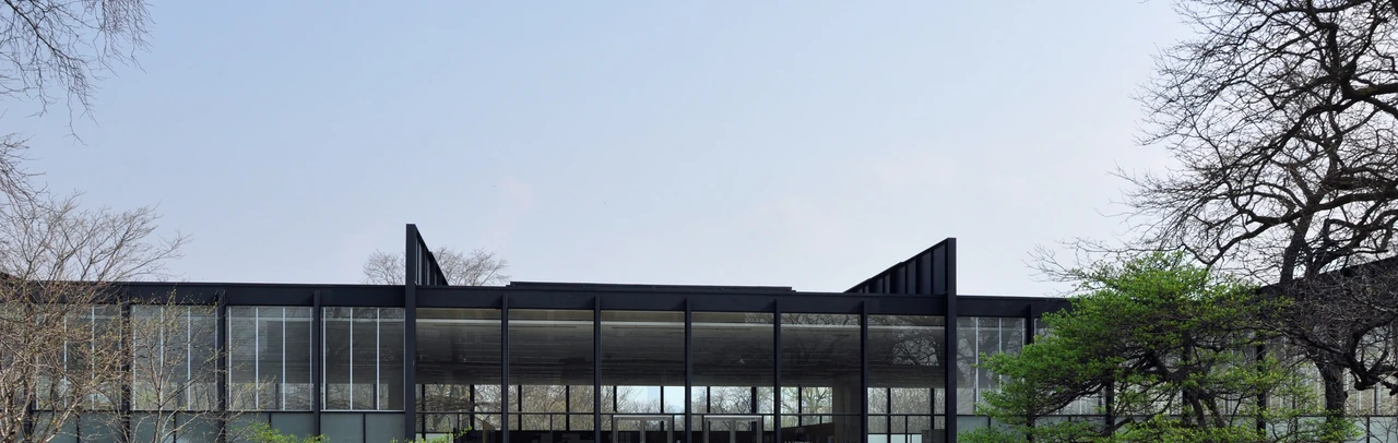
The building is not structurally empty below that roof. Its reinforced-concrete lower substructure is independent of the main upper steel frame. The principal floor sits about six feet above the surrounding ground, allowing clerestory light to reach the lower level. Workshops, lecture rooms, offices and services occupy that level, with the library introduced later. The apparently universal upper room is sustained by a more conventionally divided supporting programme beneath it. [11]
The upper interior also has a deliberate organisation. Low oak partitions shape zones without cutting off the overall view, while stairs and service chases interrupt the open floor in controlled positions. The ten-foot planning module belongs to Crown Hall's design and should not be confused with the larger grid described for other IIT buildings. Flexibility here means a carefully composed teaching environment, not the absence of every fixed element or the freedom to alter the building without consequences. [11]

Text alternative for the diagram
Crown Hall’s column-free upper teaching room and independent lower structure are different spatial systems. Original diagram of their relationship, not a measured building section.
- Crown Hall: open room, occupied section
- Conceptual — not measured
- Upper hall
- Exterior steel support carries the roof without interior columns.
- Lower level
- Independent reinforced- concrete support contains a divided programme.
- Interfaces
- Glazing, partitions and services qualify the image of unlimited open space.
Glass establishes further distinctions. The historical description identifies upper clear panels, a middle translucent zone and lower clerestories, with ventilation and solar control serving the occupied rooms. Black-painted steel and ground-down welds give the external frame a continuous-looking line, but the craftsmanship does not remove the joints. The ceiling similarly looks like a single plane while accommodating acoustic tiles, lighting, ventilation and sprinklers. The abstract image has a working environmental assembly behind it. [11]
Environmental requirements changed. Planned air conditioning was not installed at the outset and was added later; glazing and partitions also had their own histories. The 2000 landmark nomination records one stage in that development. Its floor plans and glazing elevations preserve arrangements and distinctions that a general view of the building cannot fully explain. Crown Hall's outward clarity has accommodated changing requirements, rather than remaining an unaltered object outside the history of occupation. [11]
The completed 2005 restoration addressed appearance and performance together. Gunny Harboe's account describes collaboration with Krueck & Sexton and environmental consultants, during a concentrated fifteen-week school break. The glass then in place included 1970s replacements rather than the original glazing. Full-sized mockups helped evaluate new work; the selected sealed, sandblasted glass and revised glazing details sought to recover historic appearance while addressing the requirements of that intervention. [12], [13]
Double and triple glazing were considered but rejected for this conservation project. That decision was a trade-off involving profiles, appearance and the building's significance, not a general argument against insulating glass. Professional lead-paint remediation and experienced glaziers were equally consequential. Conservation of a steel landmark depended on people working through coatings, glass edges and interfaces, not only on preserving the great exterior roof supports. [13]
Seagram: the steel frame and its bronze image
The Seagram Building in New York separates the actual frame from the image of framing with particular clarity. Its 1956–58 construction combines steel structure, bolted connections and wind trusses with protective encasement. Exterior structural members were protected by concrete, while gypsum participated around interior supports. The bronze I-shaped extrusions on the façade express a framing vocabulary, but they are not the primary steel columns that carry the building. [10]
This distinction changes what it means to call the façade honest. It is not a direct exposure of every load-bearing member. It is a carefully made architectural representation, with a selected metal, colour, rhythm and degree of uniformity. Protected steel behind the skin and bronze outside perform different tasks. The wall communicates a structural order while remaining an enclosure designed in its own right. [10]
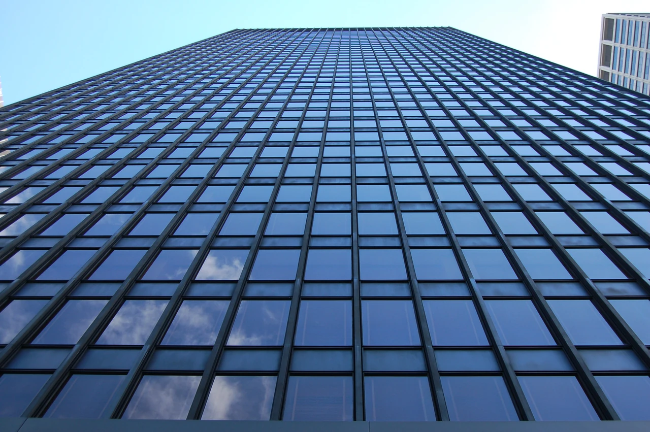
The work was collective. Mies van der Rohe and Philip Johnson worked with Phyllis Lambert, the associate practice of Kahn & Jacobs, structural engineers, services consultants, lighting expertise and the contractor. The tower's modules and interior organisation belonged to a substantial commercial programme, while the plaza and rear masses adjusted its relationship to the city. The frame supported these choices; steel did not require that every tower adopt them. [10]
The exterior's consistency also depended on management. The designation report describes regulated positions for blinds and a particular early night-lighting arrangement. Its 1989 notes say that the latter had not been used since the 1970s. The familiar image was never simply the spontaneous result of an exposed skeleton: furnishing, lighting, maintenance and occupation helped sustain or change it. [10]
The plaza occupied a substantial share of the site rather than maximising the tower's footprint across it. This urban gesture made the office building's relationship to Park Avenue part of its architecture. Lambert's later personal and scholarly history, Building Seagram, is a useful counterpart to technical accounts because it follows the building's cultural and urban legacies alongside its making. The frame belongs to the history of clients, land and public presentation as well as to engineering. [10], [34]
Neue Nationalgalerie: an apparently flat roof
At Berlin's Neue Nationalgalerie, Mies placed a glazed square hall beneath a much larger steel roof. The grillage measures approximately 64.8 metres on each side, divided into an eighteen-by-eighteen field of 3.6-metre cells. Eight steel columns support it; the glass wall sits farther inward. The cantilevered perimeter and inset enclosure allow the roof to read as a continuous floating plane while the hall remains open towards the terrace. [14], [18]
That apparent flatness required deliberate shape. In the museum's interview with construction manager Heinz Oeter, the welded roof incorporated a slight upward camber to address deflection and the desired straight appearance. Optical order and structural behaviour were coordinated rather than identical. What a viewer perceives as a perfectly level steel surface can be the result of carefully anticipated movement under its own weight. [14]
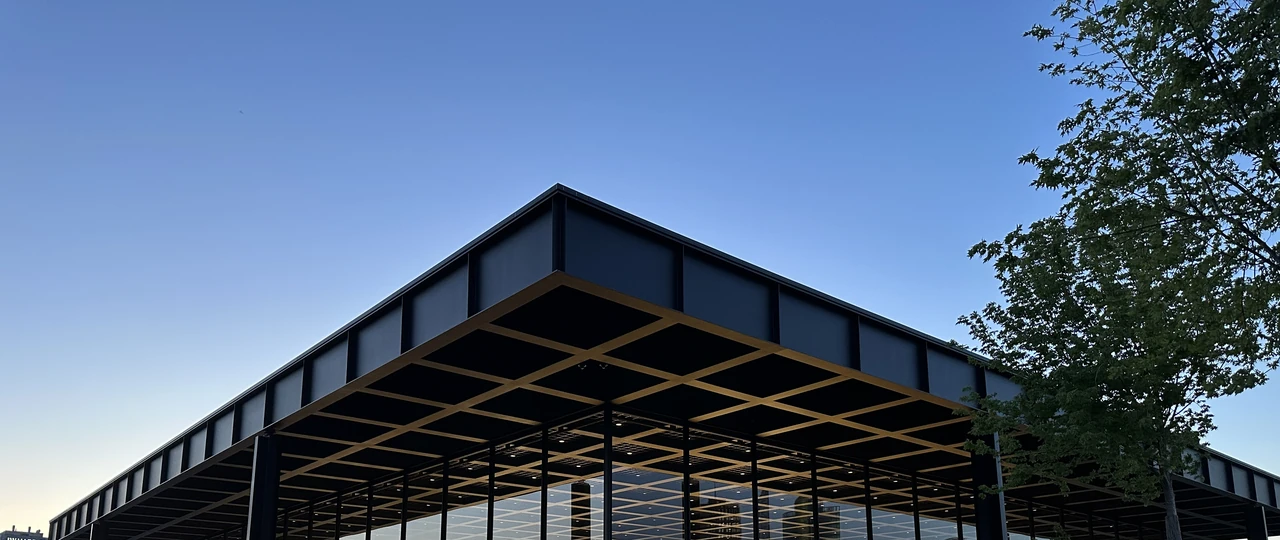
Fabrication and erection were major undertakings. Welders assembled the immense grillage, and the coordinated roof lift took place on 5 April 1967, before the ceremony a week later. Temporary equipment and synchronised work made the completed form possible. Behind the museum's apparently effortless floating roof lies the history of specialist fabrication, controlled lifting and carefully coordinated construction labour. [14]
The hall also belongs to a larger museum section. Galleries, administration, library and storage occupy the substantial plinth below, with an enclosed sculpture court adjoining the museum. The statutory heritage account relates the building's temple-like form to the classical architectural tradition and Schinkel, while recognising the tension between monumentality and transparency. Alexander Calder's steel sculpture and Henry Moore's bronze work on the terrace are separate artistic objects, their organic forms set against the roof's strict geometry. [18]
Steel and glass did not make the enclosure environmentally effortless. The museum's 2017 conservation account links thermal bridges and condensation to corrosion, while frame movement and glass breakage required attention at the interfaces. Proposed approaches ranged from retaining the historic structure with revised glass to replacing it with a thermally broken system. Altered profiles and lost historic fabric were part of the cost of the more extensive options. [15]
Proposed movement posts and changed glass-to-roof details illustrate why a rigid-looking façade needs room for thermal movement. These were planning-stage explanations, not proof that every illustrated option was later executed. The broader completed restoration, carried out during the 2015–21 closure, addressed glass, fire precautions, concrete, services, accessibility, storage and other museum requirements. The building reopened in August 2021; its apparently flexible hall did not exempt it from a demanding conservation programme. [15], [16]
The composite floor required its own investigation. A steel-coffered reinforced-concrete deck contained reinforcement whose placement complicated assessment. Monitored tests of selected exterior and interior areas helped establish behaviour and avoid blanket strengthening. Their value lay in investigation of particular areas for particular needs, not a timeless permission to place any heavy artwork anywhere. Roof, floor, glass and occupation each required their own understanding. [17]
Centre Pompidou: the connection becomes architecture
The Centre Pompidou in Paris makes the node almost as recognisable as the beam. Its cast-steel gerberette acts as a lever between a column, a long spanning beam and an external tie. The tie's route towards the foundations balances the support arrangement; the visible parts participate in a force path rather than merely ornamenting the edge. Peter Rice's engineering contribution made the connection a central architectural subject. [19], [20], [21]
Repeated frames organise the building. Fourteen main portiques form thirteen bays, while reinforced-concrete slabs supply the floors. Enormous diagonal crosses across the long façades and horizontal bracing contribute to stability. The result is neither a steel-only interior nor a collection of spectacular independent components. Floor, brace, column, beam and connection cooperate in the repeated assembly. [19], [20]
The distinction between primary and replaceable work was deliberate. The glass façade lies behind the exterior columns and gerberettes, attaching a tertiary enclosure to the more permanent principal structure. Freed floor plates offered room for different arrangements, but the existence of a replaceable skin did not make every later change simple or limitless. The structure establishes possibilities and constraints simultaneously. [19], [20], [21]

Text alternative for the diagram
Pompidou’s frame is an assembly of distinct supporting and enclosing roles. Original non-dimensional relationship sketch, not a literal gerberette detail or construction instruction. Its historical water-filled-column protection later changed to protective paint.
- Pompidou: roles around a connection
- Conceptual — not measured
- Node / beam / tie
- A cast-steel gerberette joins a lever arrangement with column, beam and tie.
- Slab / bracing
- Concrete floors and braces cooperate with repeated steel frames.
- Inset enclosure
- The glass layer is distinct from the principal exterior structure.
Manufacture widened the geography of the building. Large steel components came from specialised industrial suppliers, including Krupp's German steelwork, while delivery and erection brought them into the dense Parisian site. Piano's retrospective account describes their movement through the city at night; the museum's later history also recalls the procurement's political sensitivities. Service pipes from Fumel belong to another manufacturing contribution and should not be confused with the primary structural members. [19], [21]
The hollow columns arrived in three sections and were welded on site. Cast steel at the nodes, long beams, ties, concrete slabs and glass required different production and handling processes. An assembly that looks like an enormous construction toy nevertheless depended on heavy industrial work and precise coordination. Its repetition is architectural order built through a complicated supply chain, not automatic interchangeability at every point. [19], [20]
The fire-protection history exposes another difference between visible and bare steel. The original system used water and glycol in the hollow columns. According to the Centre's later account, special protective paint replaced that arrangement in the early 2000s. A historical description of water-filled columns is therefore not a complete account of their later condition. Protective coatings can coexist with the desired exposed appearance. [19], [21], [27]
The façade also displays relationships between occupants and the city. The transparent western side and public circulation make movement visible against the piazza, while technical services gather at the rear. Not every conspicuous pipe is a structural member. The architectural image brings together support, circulation and equipment as distinct kinds of work. The piazza's openness was part of a social intention, not a permanent statement of every later admission arrangement. [19], [20]
The building began changing early. Its 31 January 1977 inauguration and 2 February public opening are separate milestones; the tenth-anniversary dossier records interior alterations during the 1980s. Later renovation plans continue that history. Steel's capacity to span broad floors made adaptation possible, but its survival includes carefully negotiated changes in use, layout, protection and cultural expectations. [20], [21]
Sendai Mediatheque: tubes, floors and services
Sendai Mediatheque gives the steel frame a markedly different figure. Its owner's Japanese description identifies thirteen independent steel shafts, chiefly made as tubular trusses, cooperating with six flat honeycomb floors formed from steel-plate sandwich construction. Instead of a uniform cage of identical vertical columns, the building distributes support and circulation through conspicuous tube-like structures and differently planned levels. [22]
The shafts carry services and vertical movement as well as participating in the structural organisation. Networks, environmental equipment, lifts and stairs are coordinated with the tubes, without every shaft having an identical content. The system makes the relationship between support and building operation a visible architectural theme. The floor is not simply a conventional slab placed over an otherwise independent collection of pipes. [22]
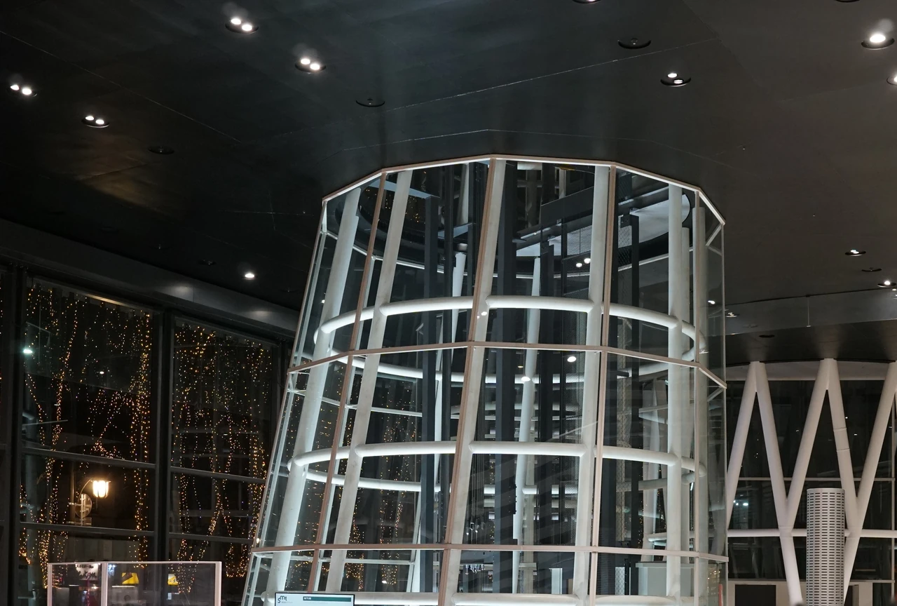
Its construction is mixed. The owner's data identify steel with some reinforced concrete, two basement levels, seven above-ground levels and a roof, as well as a basement energy-absorption mechanism. Those particulars are more informative than calling the whole building earthquake-proof or assuming that a description of an intended mechanism establishes its performance in every later event. The principal architectural design by Toyo Ito's office worked with Mutsuro Sasaki's structural practice, municipal supervision and several contractors. [22]
The southern double-glass façade also has an operating cycle. In summer, openings allow rising air to help cool the glass; in winter, closing them forms an insulating air layer. Environmental control belongs to the occupied steel-and-glass building, rather than arriving as an unrelated technical addition. The recorded handover in August 2000 is a construction milestone, distinct from any subsequent public opening. [22]
Prefabricated steel in Congo: factories and colonial networks
Belgian prefabricated buildings in Congo reveal a history outside the familiar sequence of American towers and European museums. Aris Mpemba Nkole Kabongo's 2026 engineering dissertation, developed through architectural and structural collaboration, studies GCE buildings and the former hotel at Thysville, now Mbanza-Ngungu. It combines archive material, surveys and modelling with proposed rehabilitation. The buildings are physical survivals of industrial trade and colonial occupation, not evidence that architectural history began with their importation. [23], [24], [25]
The systems need to be distinguished. Danly buildings used sheet-metal construction, while GCE combined a steel framework with timber, brick and concrete. Rolled beams and columns, angles and fasteners organised repeatable components; foundations and infill involved other materials and local work. Describing all the exported architecture as steel erases differences in manufacture, climate performance and structural behaviour. [24]
GCE's Hoboken workshops prepared connections with shop-riveted cleats, leaving bolted assembly for the site. Trial erection checked the frame before shipment. A photograph of the Kinshasa ABC frame assembled at Hoboken consequently documents factory preparation, not building erection in Congo. Prefabrication shifted some labour upstream but did not deliver a completed occupied building directly from the ship. [24]
Sea transport from Antwerp to Matadi and onward railway movement linked factories to distant projects. Interconnected industrial, shipping and railway interests helped organise those networks. Yet rail transport did not eliminate human portage on the last leg to individual sites. Claims about a particular vessel require more than a plausible commercial connection; the broader network is better established than every frame's precise itinerary. [24]
This logistics had a political and human cost. The Royal Museum for Central Africa's interpretation of colonial railway history describes exhausting work, poor conditions, escape and construction deaths, while emphasising that portage continued after the railway. Images of efficient transport and industrial progress can omit violence, segregation and resistance. The frame arrived within an extractive economy and an unequal regime, not a neutral story in which European machines brought life to empty land. [24], [25]
Mbanza-Ngungu's earlier settlement history matters to that correction. Nsōna-Ngungu predated the colonial renaming, while railway workshops and the 1906 hotel belonged to subsequent development. The studied hotel is also distinct from Kinshasa's 1912 ABC building and Matadi's 1915 hotel. Specific names and dates locate the architecture without making colonial commercial claims into an account of the origins of Congolese society. [24]
Climate shaped the imported components. Shaded verandas, raised floors, openings and ventilated double roofs addressed the tropical environment, while some GCE buildings included roof lanterns. Thin double-sheet walls could nevertheless become hot; corrosion and repainting complicated claims of permanence. The arrangement expressed a set of environmental intentions and colonial occupancy requirements, not an inherently superior answer to every local building tradition. [24]
Locally constructed masonry or concrete foundations formed part of the assembly. Even where some constituents were imported, it would be wrong to call every material European. Raised floors served ventilation and historical health ideas, but nineteenth-century miasma explanations are not valid accounts of malaria. The architectural features can be described without endorsing the science or racial hierarchies sometimes used to promote them. [24]
A mixed frame's changing life at Mbanza-Ngungu
The studied hotel contained a central masonry system and steel-framed verandas beneath its roof. Reconstructed original plans place rooms within an arrangement of surrounding verandas, end stairs and raised foundations: circulation, shading and support were coordinated rather than separate inventions. The dissertation's tributary-area estimate assigns roughly seventy per cent of gravity load to the central masonry, with the steel veranda system carrying the remainder and roof work. That is a scoped estimate, not an instrumented measurement of every building's loads. It makes clear that walls described as infill in one frame cannot automatically be treated as removable partitions in another. [24]
Floors combined steel with timber joists, brick jack arches and concrete. In the actual studied arrangement, the brick arches lacked the ties shown in a general nineteenth-century handbook example. A historic textbook drawing and a surveyed building do not necessarily depict the same assembly. The building's mixed materials determine how work passes between members; replacing a floor changes more than the surface on which people stand. [24]
Several details served overlapping purposes. Shaped brackets could support verandas and overhangs while contributing ornament. Expanded-metal grids in roof gaps could assist restraint, allow ventilation and restrict pests. Roof ties contained rafter thrust, and the studied roof included X-bracing. The absence of a separate façade-bracing system in one description should not be mistaken for the absence of all stabilising work. [24]
The central core, floors and subsidiary elements participated together in stability. Original and later arrangements had different load paths, as did a bare erection frame and a completed occupied building. Connection types likewise differed: shop rivets, field bolts, timber screws, web angles and base details cannot be collapsed into a generic picture of all early steelwork. Some floor connections provided meaningful rotational restraint, while others were better represented as pinned. [24]
Material identification also has limits. A surveyed member's CL.ACIER stamp supports its identification as steel, but the study's strength assumptions do not certify every historic component as a modern grade. Bolt marks, inaccessible fasteners and uncertain roofing metal require separate judgement. An old sheet that looks like metal might be iron or steel; a convenient modelling approximation is not a laboratory test of the original alloy. [24]
Alteration did not begin only after colonial rule. An archive-backed hotel phase around 1926 changed parts of the accommodation, while later courthouse use enclosed verandas with additional masonry. Timber ground-floor construction was replaced by reinforced concrete, and removal of a column led to a transfer beam. The frame's history contains several decisions about occupation and support; blaming every change on later users would erase earlier interventions. [24]
Additional walls imposed loads on members not originally intended for them. Damaged roofing and drainage brought water onto steel, while water and dust traps worsened exposure. Missing fasteners were observed, but corrosion as their direct cause could not be proved from observation alone. Deterioration, changed loads and connection condition can act together without one simple explanation accounting for every defect. [24]
Local and whole-building problems also differ. In the dissertation's model, the central system maintained overall stability even where later veranda walls harmed particular beams. Allowing for joint restraint did not resolve all the affected beams' problems, and one column also required particular attention. That does not establish a general verdict on safe occupation. Atmospheric-corrosion predictions in the study were theoretical and lacked the experimental data required to treat them as measured present losses. The distinction preserves the usefulness of the analysis without turning it into an unsupported remaining-life forecast. [24]

Text alternative for the diagram
The Mbanza-Ngungu hotel’s central and veranda systems shared work. Approximately 70% is the dissertation’s tributary-area estimate, not an instrumented measurement; later loads changed particular members’ demands. Original schematic, not a measured plan or occupation assessment.
- Mixed support changes the reading of a frame
- Conceptual — not measured
- Central support
- The hotel study estimates roughly 70% of gravity load on central masonry.
- Cooperating floors
- Steel, timber, brick arches and concrete make different coupled systems.
- Later walls
- Added veranda masonry can harm individual members despite overall model stability.
Proposed rehabilitation consequently combines repair of roofing and drainage, professional coating assessment, retention, strengthening and selective replacement. Compatible geometry, surrounding damage, renewed floor or roof action and available joining skills affect the choices. Toxic constituents in old finishes, trials, access and waste require specialist attention. A coat of paint alone cannot recover a changed load path, while replacing every historic member can lose the material record the project seeks to preserve. [24]
Affordability and local capacity are part of the proposal. The dissertation distinguishes important public cases from domestic pavilions whose solutions must be workable with available resources and skills. Familiar bolted prefabrication may assist reversible work, but steel is not presented as the unavoidable answer to every heritage building. The proposed intervention requires further study before execution; it is not an already completed restoration. [24]
Field missions in 2020, 2021 and 2023 involved University Kongo researchers and local administrative and workshop participants. A later seminar elicited ideas including continued administration, a library or museum, housing for retired transport workers, and attention to neighbourhood memory. Further inventories of the surviving stock, research on connector corrosion and investigation of pavilion joints would extend the work beyond one hotel. Continued use, maintenance and funding belong together. The future of the frame concerns people who live with it, not only the distant factory that supplied it or the analyst who models it. [24]
Fire, moisture and the protected frame
Steel's non-combustibility describes its contribution as fuel; it does not mean that a member retains its normal behaviour in a severe fire. Heating changes strength and stiffness, causes expansion and can produce uneven temperatures across sections and floors. Slender conductive steel can heat quickly. Loss of useful capacity or damaging deformation does not require the metal to melt. [27]
Protection becomes part of the architecture. Concrete or masonry encasement, gypsum and mineral boards, sprayed materials and intumescent systems take different approaches to delaying heating or absorbing heat. Expanded char can protect a surface that otherwise looks exposed. Weight, profile, finish, access and maintenance all enter the decision. A façade of visible painted steel may therefore show the member's form without showing it bare. [10], [21], [27]
A fire rating belongs to a tested or assessed assembly rather than to steel as an abstract universal property. Geometry, exposed perimeter relative to mass, surrounding construction and restraint affect the result. Proprietary products can have public ratings without every detail of their temperature-dependent behaviour being publicly available. These distinctions explain why the phrase fireproof steel can conceal more than it tells. [27]
Connections participate in the changing response. A sheltered or massive joint can heat differently from the member it joins, while expansion can alter the forces it must carry. Composite floors develop temperature gradients and differential movement; bowing and potential tensile or catenary action depend on continuity, connections and the surrounding frame. None is an automatic guarantee that a heated building survives. [27]
The 2010 NIST guide discusses material behaviour alongside structural-system response and recounts major research on composite floors. Its account is useful for those mechanisms, without making the dated guide a present-day design instruction. Protection can also be damaged by later trades or become inaccessible. Inspection and maintenance sustain an assembly's intended behaviour after its original construction. [27]
Moisture similarly crosses material boundaries. Harboe's comparisons of Wishnick and Siegel Hall show how different sill assemblies can allow corrosion behind apparently sound finishes. Looking only at the painted face misses the route by which water enters and remains. Mockups help test changes to profiles and interfaces before committing to a conservation intervention. [13]
His account of Chicago's 860–880 Lake Shore Drive describes investigation of windows, underlying steel, concrete, drainage and interacting metals. Stainless cladding installed earlier had not by itself solved water entry. Retention of serviceable windows and attention to the adjoining assembly offered a more precise response than assuming every visible finish needed replacement. [13]
Neue Nationalgalerie and Crown Hall add different conservation choices. Condensation, thermal movement, glazing geometry and hazardous old coatings required project-specific work; acceptable appearance and environmental performance were not settled by a single preferred product. The same apparently simple steel-and-glass vocabulary can demand different interventions in different buildings. Conservation begins with the actual interface, not with a universal rule that old frames should be exposed, insulated, replaced or left untouched. [13], [15], [16], [17]
Ordinary halls and the possibilities of reuse
Steel frames are often most economically legible in industrial halls. Portal frames or girders carried by columns produce repetitive bays and broad working spaces. Bolted assembly can make separation possible, particularly where members and connections remain accessible. These ordinary buildings place the frame in storage, manufacturing and logistics rather than treating it primarily as a skyline or museum image. [28]
Several different actions are called reuse. Keeping a frame in place retains a building's support in its original setting. Moving an assembled building differs from dismantling it into components and reconstructing it elsewhere. Selected members can enter a different structure; unused fabricated stock can find a buyer after its original project is cancelled. Recycling scrap by melting it preserves material feedstock but not the previous member, fabrication or building arrangement. Those distinctions matter to architectural continuity as well as to environmental assessment. [28]

Text alternative for the diagram
Retention, movement, reconstruction, member recovery and unused fabricated stock retain different work. Scrap remelting is a separate action. Actual next use, documentation and assessment determine what is realised. Original conceptual flow.
- Five different next lives
- Conceptual — not measured
- Keep in place
- Programme changes; existing support stays.
- Move assembled
- Short transport can preserve the assembly.
- Dismantle / rebuild
- Frame may travel; envelope can change.
- Recover members
- Old pieces combine with new work.
- Unused surplus
- Fabricated stock has not served a building.
- Scrap remelting is different
- Metal feedstock remains, not the old member or its joints.
The ADVANCE research consortium's 2024 case report documents relocation with altered envelopes and layouts. A SEGRO warehouse at Slough, erected in 2000, was moved in 2015 with a different layout to enable a road-bridge project; its brick cladding gave way to a new wall system. Agrocolumna's warehouse and office moved from Craiova to Copăceni with an additional bay. A canopy moved from Pula to Otočcu. The frame could travel without every enclosing material or aspect of the programme remaining the same. [28]
Distance and scale introduce different logistics. The report describes a frame moved from the United States and redesigned for a Romanian production hall, while a Helsinki harbour warehouse travelled a short distance without disassembly. Amsterdam's Braziliëloods frame was dismantled, recoated and reused after long service. Historic relocation of the great Cardington No. 2 hangar supplies another large-span example. Secondary joists and cladding can prove more difficult to recover than the primary frame, so even a successful move may preserve unequal amounts of the original assembly. There is no single practical meaning of moving a steel building. [28]
Storage can intervene between lives. Honda's Swindon warehouse, erected in 2001, was dismantled in 2004, stored for eighteen months and reconstructed in 2005. Its principal frame, baseplates and cold-rolled components were recovered, but changed use and requirements prevented reuse of the original cladding. The distinction between principal structure and secondary enclosure is not merely theoretical: it can determine what travels and what has to be remade. [28]
Programme can change too. Helsinki's temporary Hakaniemi market was moved for use as an outlet at Tuuri. At Bradford, two existing portals were incorporated into a school dining and kitchen area, with strengthening columns required in parts. Four older kit frames were assembled into a new complex at Sibiu in 2019, with some re-engineering for additional floors. Adaptability meant assessed intervention, not simply returning every member to service unchanged. [28]
Retaining a structure on its site is another opportunity. The report describes the reinforcement and conversion of a 1960s HIDROTIM industrial hall into a five-storey office in 2004, and adaptation of RWTH's former heat and power plant as seminar accommodation. Montreal's Angus workshops accommodated community, light-industrial and office uses. Their continuity lay partly in retaining the physical frame within a changing place, rather than moving it into an entirely new context. [28]
Reuse can be selective. Recovered tubes or beams may be combined with new steel suited to particular connections, while oversized members can be adapted or spliced. The Thirsk NTS building of 2017 used part of a fabricated lot from an order cancelled in 2008: that was unused surplus rather than steel salvaged after occupation. Percentages stated for a project's steel content do not automatically describe the materials of the whole building or establish its full carbon result. [28]
Some structures deliberately anticipate travel. The MEXX DAY standard-kit hall was erected in 2009 and relocated in 2017. A YIT warehouse was erected in Finland and twice in Britain, changing foundations and covering while retaining its frame. By contrast, the Petite Maison demonstration's components were dismantled in 2023 and stored for future use. Storage records preparation for a possible next life, not proof that the next building already exists. [28]
Not every opportunity is realised. The report describes unsuccessful proposals at Meridian Water in London, where extra dismantling time, costs and the scope of an older reuse protocol created obstacles. Another proposed recovery involved 1950s steel encased in concrete and was abandoned. A frame's physical potential, documentary eligibility, programme and market need to align. A particular protocol excluding older material does not prove that every pre-1970 frame is physically incapable of reuse. [28]
Other cases remain prospective in the report. The Gennevilliers riding arena, inspected in 2023, was intended to become a sorting-centre canopy at Épinal. That stated intention should be distinguished from the report's completed relocations. The history of reusable architecture includes cancelled projects, stored components and unresolved proposals, not only the successful images of reconstructed frames. [28]
Designing a second life: floors, information and trade-offs
Standardised spans and members, clear joints, accessible bolts, renewable protective finishes and separation of materials can improve a frame's prospects for disassembly. They make particular future actions easier to imagine and organise. They do not guarantee that a later owner will need the same members, that suitable documentation will survive, or that dismantling will fit the programme and budget. [28], [35]
Material knowledge is part of that future architecture. Provenance, geometry, exposure history, damage, old coatings, qualification and weldability affect whether recovered members can serve a new role. Inspection and testing consume time and resources. Unknown steel cannot become a certified modern grade simply because its section looks familiar. Records preserve useful work alongside the material, reducing uncertainty without removing the need for professional assessment. [24], [28], [35]
Composite floors show why the frame's bolts alone are insufficient. Shear connections make a steel beam and concrete slab cooperate; conventional welded studs also make their later separation difficult. Research on demountable composite construction examines specifically removable shear connectors, including bolted and coupled arrangements. The important question is the connection between beam and slab, not merely whether the beam can be unbolted from its column. [35]
Recovering the beam while replacing its slab is different from recovering both. A slab divided into segments can lose the continuity that supported diaphragm action, and its next use may require redesigned joints or additional material. A new topping can bring additional weight and complicate another later cycle of disassembly. Composite construction is therefore neither automatically unreusable nor automatically demountable: its details establish different possibilities. [35]

Text alternative for the diagram
Frame joints and beam-to-slab shear connections are different interfaces. Recovering slab segments also changes continuity and may need additional work. Original schematic, not a bolt, cutting, lifting or reuse specification.
- Two connections, one composite floor
- Conceptual — not measured
- Frame joint
- A removable beam-to-column bolt does not release its concrete slab.
- Shear connection
- Beam and slab cooperate here. Deliberately demountable systems address this interface.
- Slab continuity
- Dividing a slab changes continuity; its next life needs a designed response.
Connector slip, stiffness, ductility, serviceability and residual damage affect those possibilities. A bolt and a welded stud cannot be assumed to have identical behaviour merely because both transfer work between steel and concrete. The REDUCE research behind SCI's 2020 guide involved several universities and industrial partners; the pictured Bradford cellular-beam experiment is a particular test within that programme, not a universal guarantee for every floor system. [35]
Repeatable grids and compatible members can assist later assembly, while coordinated holes, identifiers and retained information help make recovered pieces intelligible. Access for inspection and separation, lifting and transport limits, storage, surface protection and the sequence of work require consideration from the beginning. The frame's second life is consequently shaped by logistical and documentary design as well as by the first building's elegant geometry. [28], [35]
Environmental claims need the same specificity. Avoiding some new production through actual reuse differs from assuming a future benefit that may never occur. Present impacts, dismantling, transport, adaptation and the boundary of an assessment must be distinguished from possible savings in a later cycle. Recycling and reuse are related but not identical accounts of retained work. Neither makes steel inherently carbon-free. [28], [35]
Costs also extend beyond the price of the first members. Extra preparation, testing, careful dismantling, transport, storage and reassembly may bring benefits over more than one use, but depend on a real subsequent demand. A steel frame's adaptability is best understood as a capacity made usable by details, information, skilled work and an appropriate programme. Those conditions explain its architectural power more precisely than a promise of effortless permanence or endless reuse. [28], [35]
Workers and the image of the frame
The naked frame is a powerful image of construction, but it can make the people doing the work appear anonymous. Lewis Hine's photograph of a worker on the Empire State Building places a seated figure on a beam against the distant city. The National Archives record dates the image to around 1930–31, while the print later circulated within the National Research Project's material on industrial techniques and employment. The worker and the frame entered both a building history and a history of representing labour. [30]
The photograph does not identify every aspect of the worker's life. Name, ethnicity, tools and working conditions should not be invented from a pose above the skyline. Its importance lies partly in the attention Hine gave to human contribution to industrial achievement. Looking at the frame as work changes the familiar story of a building rising through design genius alone. [30]
Alanis Obomsawin's Spudwrench – Kahnawake Man offers a different point of entry through a named person. The 1997 documentary follows Randy Horne, a high-steel worker from Kahnawake, and his defence of culture and territory during the 1990 Oka crisis. Construction labour appears within family, place and political life. It is not adequately explained through a stereotype of Indigenous workers possessing an innate fearlessness at height. [31]
Caroline Monnet's 2015 short Mobilize reconfigures NFB archival footage within a series concerned with Indigenous identity and representation. The act of re-editing matters: an inherited industrial image can acquire different relationships and meanings when an Indigenous filmmaker frames it anew. Alongside Hine's work portrait and the Congolese account of factories, railways and portage, it widens the frame's history beyond structural milestones to the people whose work and lives made those milestones possible. [24], [25], [30], [31], [32]
Selected chronology
| Date or period | Case or development | Distinction |
|---|---|---|
| 1885 | Jenney's Home Insurance Building, Chicago. [1], [2] | Influential transitional skeletal construction, not an uncontested pure-steel first. [1], [2] |
| 1889 | Gilbert's Tower Building, New York. [3] | Specific approval preceded 1892 express code recognition; structure combined iron, steel and bearing masonry. [3] |
| 1890–92 | Wainwright and the changing Monadnock schemes. [4], [9] | Protected skeletons and metal–masonry hybrids offered different visual and commercial solutions. [4], [9] |
| 1906 | Thysville hotel at present-day Mbanza-Ngungu. [24] | Prefabricated steel verandas/roof cooperated with masonry and mixed floors in a colonial transport network. [24], [25] |
| 1956 | Crown Hall completed. [11], [12] | Exterior steel roof support made a broad principal teaching hall column-free. [11] |
| 1956–58 | Seagram Building construction. [10] | Protected primary steel and expressive bronze façade elements were different systems. [10] |
| 1965–68 | Neue Nationalgalerie construction. [14], [18] | Cambered welded grillage, eight supports and inset glazed hall formed a particular museum section. [14], [18] |
| 1977 | Centre Pompidou inauguration and public opening. [20] | Cast-steel nodes, ties, bracing, concrete floors and replaceable enclosure made a coordinated assembly. [19], [20] |
| 2000 | Sendai Mediatheque handed over. [22] | Tubular truss shafts and honeycomb steel floors coordinated structure, services and differing plans. [22] |
| 2005 | Crown Hall restoration completed. [13] | Coatings, glass, mockups and specialised labour sustained historic appearance through change. [13] |
| 2020–24 | SCI demountable-floor guidance and ADVANCE reuse report. [28], [35] | Actual recovery depends on connections, information, qualification and viable next use. [28], [35] |
About the Recommended Reading
Peter Rice, An Engineer Imagines
Rice's autobiographical reflection explores the creative and collaborative role of engineering, making it a pertinent companion to Pompidou's cast-steel connections. Batsford lists a 2017 hardback and a 2024 ebook edition. The book places imaginative structural work within an engineer's account of architecture and collaboration. [33]
Phyllis Lambert, Building Seagram
Lambert's personal and scholarly account follows Seagram's architectural, cultural and urban legacies. Yale's historical publisher announcement identifies the book and author; it makes a pertinent companion to the landmark report's steel, bronze, plaza and client history. [34]
SCI, Guidance on Demountable Composite Construction Systems for UK Practice
The 2020 guide by Ana M. Girão Coelho, Mark Lawson, Dennis Lam and Jie Yang examines removable shear connections and the different prospects for beams and slabs. Its research-based technical preview supports deeper reading on disassembly, while its dated UK design provisions should not be mistaken for instructions for an unassessed building. [35]
Watch: workers, memory and the steel frame
Caroline Monnet's archival re-edit and Alanis Obomsawin's portrait of Randy Horne offer different perspectives on Indigenous mobility, high-steel work and the lives around the frame.
Mobilize
A short archival re-edit connects Indigenous mobility, labour, land and the industrial city through film and music.
Loading connects to the original film provider. No film is loaded before you choose to load it. The preview is an abstract editorial symbol, not a film still.
Watch at original sourceAbout the Films
Mobilize — Caroline Monnet
The NFB's 2015 short, 3 minutes 30 seconds, re-edits archival footage to address Indigenous identity and representation. Caroline Monnet directs, Anita Lee produces, Jesse Rivière edits and Tanya Tagaq contributes music. It offers a concise companion to the discussion of inherited construction imagery and labour. [32]
Spudwrench – Kahnawake Man — Alanis Obomsawin
The 1997 documentary, approximately 58 minutes, links Randy Horne's high-steel work with Kahnawake, family and defence of territory during the 1990 Oka crisis. The filmmaker's named subject offers a fuller human context than anonymous workers used only as a spectacle of height. Viewing options and regional availability are supplied by the NFB. [31]
Material Matters — Gunny Harboe
The National Park Service's record of Harboe's 2015 keynote includes Crown Hall and other mid-century conservation work. The discussion of mockups, glazing, coatings and retained components is particularly relevant to a steel frame's continuing material life. [13]
Frequently Asked Questions
No. Historic assemblies can combine cast iron, wrought iron, steel and masonry. A general label such as metal frame does not establish every member's material, and early design drawings may describe a scheme different from the completed building. [3], [4], [6], [7]
Not necessarily. Floors, braces, joints, foundations and participating walls or cores can have different roles. A building with steel gravity support may depend on concrete or masonry for other work. [19], [24], [27]
No. Seagram's bronze extrusions express a framing vocabulary without being its primary steel columns. Wainwright also distinguishes some apparent façade piers from principal structural supports. [9], [10]
No. Pompidou's cast-steel nodes use a different material from historic grey cast iron. Casting names a forming process, not one universal alloy or structural behaviour. [19], [21]
No. Cold-formed studs can be used in nonbearing partitions or in designed structural assemblies. Their intended role and connections matter more than the fact that a wall contains metal. [29]
No. Heating changes strength, stiffness and dimensions; damaging deformation or loss of capacity can occur without melting. Protection and the behaviour of the whole assembly are important. [27]
No. Specialist protective coatings can preserve a visible member's form. Pompidou's later protection history illustrates the difference between exposed appearance and bare metal. [21], [27]
No. Spans may permit broad rooms, but services, circulation, floors, enclosure and participating walls still establish constraints. Crown Hall and the altered Mbanza-Ngungu hotel show different kinds of flexibility. [11], [24]
No. Retention, relocation and recovery of members preserve different amounts of the existing assembly; melting scrap preserves a feedstock rather than the original member. [28]
Not by itself. The beam-to-slab shear connections and the continuity of the recovered slab require attention. A frame's removable beam-to-column bolts do not automatically release its concrete floor. [35]
References
- Chicago Architecture Center, Skeleton frame construction.
- Chicago Architecture Center, Home Insurance Building.
- The Skyscraper Museum, Tower Building, with attributed structural explanation by Donald Friedman.
- Thomas Leslie, Canadian Centre for Architecture, Le Monadnock n'est pas si simple, March 2017.
- Canadian Centre for Architecture, Drawings, prints, reprographic copies and documents for the Monadnock Building, fonds DR1986:0767:001–473; collection description.
- Canadian Centre for Architecture, Monadnock Block: Details for cast iron column connections, DR1986:0767:044, September [?] 1885.
- Canadian Centre for Architecture, Monadnock Building: Details for beam-to-column connections, DR1986:0767:121, printed after October 1889.
- Canadian Centre for Architecture, Monadnock Building: Plan and details for bay window brackets, DR1986:0767:234, after 1889.
- Missouri State Historic Preservation Office, Wainwright Building nomination packet, 1975 nomination/1977 signature; drawings and photographs included.
- New York City Landmarks Preservation Commission, Seagram Building designation report, LP-1664, 1989; selected description and notes.
- Eric D. Thompson/National Park Service, S. R. Crown Hall National Historic Landmark nomination, October 2000; designation 7 August 2001; selected description, plans and glazing elevations.
- Illinois Institute of Technology, Renovation of a Modernist Architectural Icon, May 2005 announcement on a 2014-posted page.
- National Park Service, Material Matters: Mid-Century Modern keynote, Gunny Harboe, 2015 presentation; selected original transcript.
- Staatliche Museen zu Berlin, Optisch gerade, aber doch gebogen: Das Dach der Neuen Nationalgalerie, 2017 interview with Heinz Oeter.
- Staatliche Museen zu Berlin, Schwierige Verbindung: Die Stahl- und Glasfassade der Neuen Nationalgalerie, 2017 planning account.
- Staatliche Museen zu Berlin, Neue Nationalgalerie: Sanierung, completed 2015–21 restoration.
- Staatliche Museen zu Berlin, Der Deckenbelastungstest für die Neue Nationalgalerie, 2017 account of selected floor tests.
- Landesdenkmalamt Berlin, Neue Nationalgalerie, monument 09050310, original statutory record and historical description.
- Centre Pompidou, Structure et modules, French architectural teaching resource.
- Centre Pompidou, Tenth-anniversary press dossier, 1987; selected architecture, opening, assembly and early-alteration pages.
- Centre Pompidou, Secrets d'archi: L'exosquelette métallique du Centre Pompidou, 1 December 2025.
- Sendai Mediatheque, 建築の特徴 — Architectural characteristics, original Japanese structural/environmental description and construction data.
- Université de Liège, ORBi, Aris Mpemba Nkole Kabongo dissertation record, August 2026 engineering study and bibliographic scope.
- Aris Mpemba Nkole Kabongo, Original French engineering dissertation, August 2026, 482 PDF pages; selected GCE construction, field, hotel, corrosion, joint, rehabilitation and conclusion chapters.
- Royal Museum for Central Africa, Congo Panorama exhibition dossier, 2025; selected critical interpretation of colonial railway, portage and extraction imagery.
- James Potterton, California Polytechnic State University, Seismic Evaluation of Steel Frame Buildings with Unreinforced Masonry Infill Walls, 2009; original university abstract and metadata only.
- National Institute of Standards and Technology, Best Practice Guidelines for Structural Fire Resistance Design of Concrete and Steel Buildings, TN 1681, November 2010; selected steel, protection and structural-response pages.
- RFCS ADVANCE consortium/European Convention for Constructional Steelwork, Circular Economy of Steel-Based Building Components, D2.1, May 2024; selected qualification, design-for-reuse and case-study sections.
- Steel Framing Industry Association, BuildSteel, Cold-Formed Steel Framing 101: A Practical Guide, 29 January 2026; forming process, member anatomy and structural/nonstructural distinctions.
- National Archives Foundation, DocsTeach, Workman on the Framework of the Empire State Building, Lewis Hine, ca. 1930–31; NARA 518290/69-RH-4K-1; item attribution, collection and rights record.
- National Film Board of Canada, Spudwrench – Kahnawake Man, Alanis Obomsawin, 1997; original film record and credits.
- National Film Board of Canada, Mobilize, Caroline Monnet, 2015; original film record and credits.
- Batsford Books, An Engineer Imagines, Peter Rice; 2017 hardback ISBN 9781849944236 / 2024 ebook ISBN 9781849944663; publisher record.
- Yale University Press, Building Seagram publisher announcement, 12 February 2014; Phyllis Lambert book identity and described scope.
- Ana M. Girão Coelho, Mark Lawson, Dennis Lam and Jie Yang, SCI, Guidance on Demountable Composite Construction Systems for UK Practice, P428, 2020, ISBN 9781859422458; selected original guide pages.
Explore RELATED Architecture
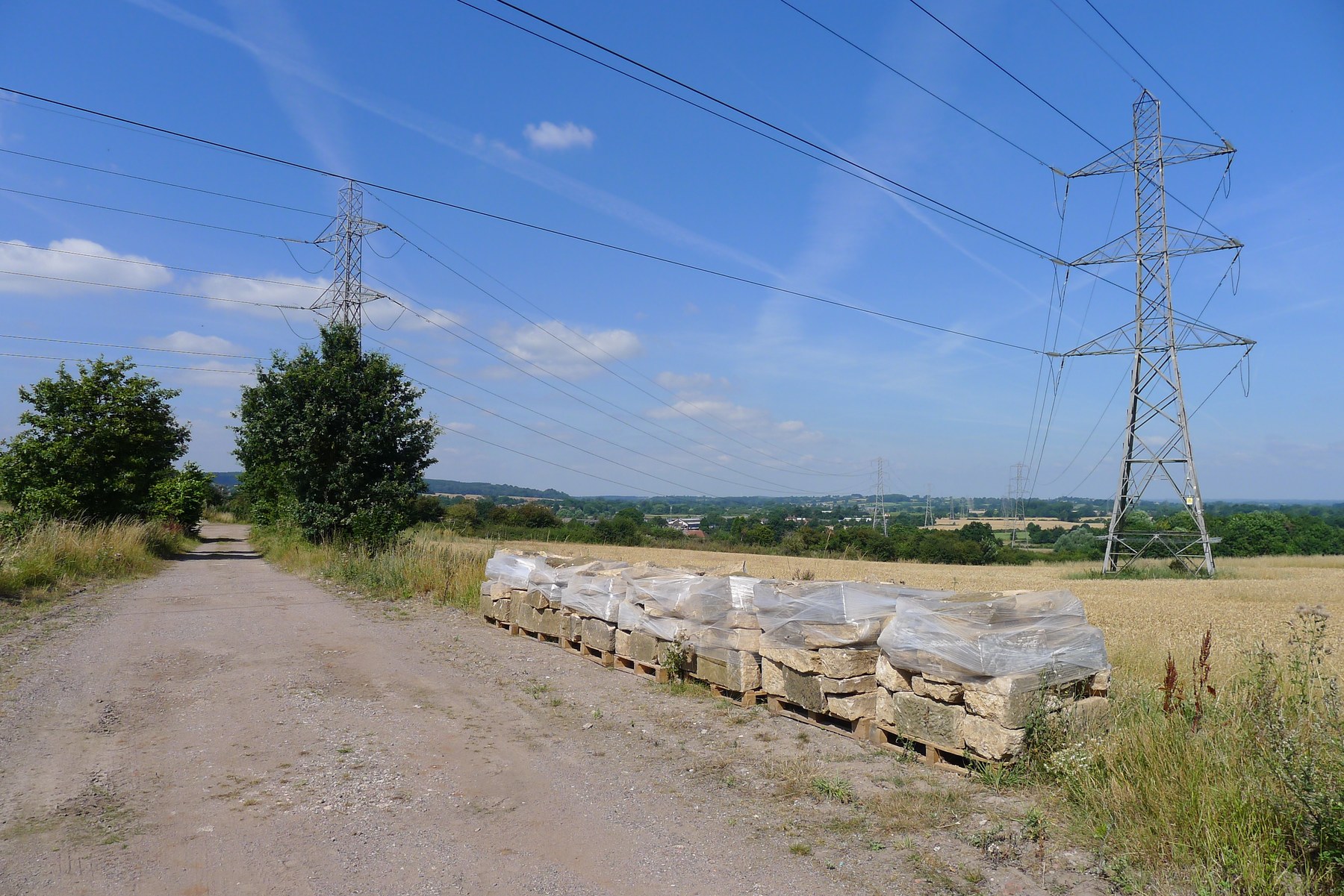
Architectural Materials
Materials, assemblies and the different lives of building components.
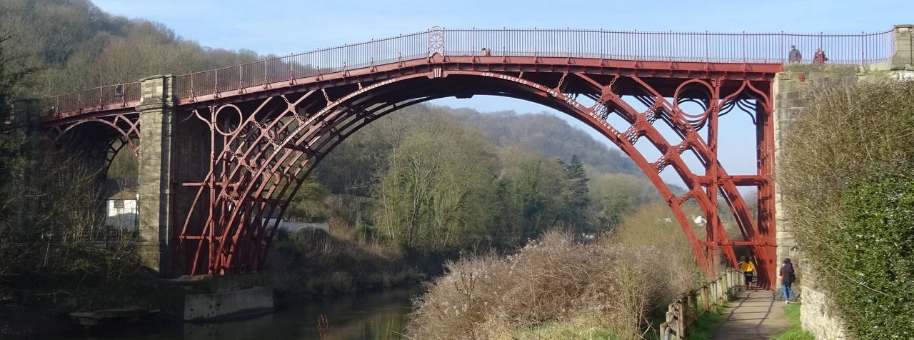
Cast Iron
Casting, historic iron frames and the joints that distinguish another material history.
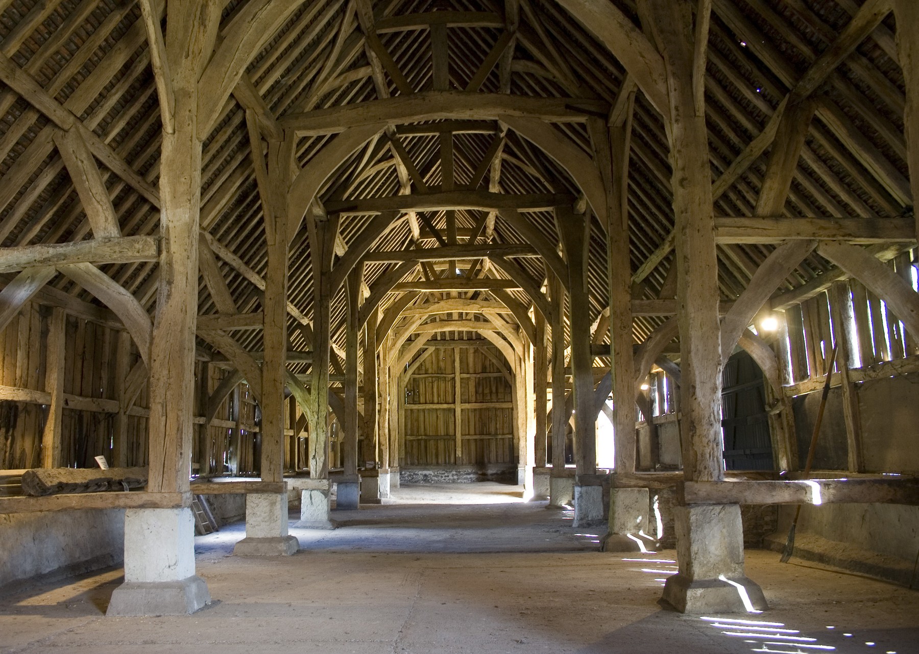
Timber Framing
Timber posts, braces and floors that cooperate with other materials.

Stone Masonry
Bearing stonework and worked contacts in mixed-material buildings.
Ashlar Masonry
A dressed architectural frontage is not necessarily its supporting skeleton.
Brick
Brick bearing walls, enclosure and the changing work of masonry.
Gothic Architecture
Slender supports and pointed forms realised in materials beyond steel.
Architectural Sections
Sections reveal levels and assemblies that façades can hide.