


 by Tom Gurney
Tom Gurney BSc (Hons) is an art history expert with over 20 years experience
Email: tomgurney1@gmail.com / Phone: +44 7429 011000
Cut, Space, Proposal and Record
An architectural section imagines a building cut so that a relationship concealed by its exterior can be seen on a drawing. The cut might pass through a stair, nave, theatre auditorium, roof or wall junction. It can reveal floor-to-floor height, the path from one level to another, the thickness of masonry, the span of a roof or the way light enters an interior. Yet a section is not simply a picture of what would appear if a building were sawn open. The draughtsman chooses a cut plane, a direction of looking, what to draw beyond the plane, a scale and a level of finish. A single slice can clarify one space while omitting another. Some historical sheets called sections are coloured room views; others are perspectival cutaways, printed reconstructions, proposed designs or later measured records. Each offers a different kind of architectural evidence. [1], [4], [8], [12], [16]
One of the most revealing cases is a building whose drawing history survives in several types of section but not as a perfectly matching set. At San Firenze in Florence, an Uffizi study counts twenty longitudinal sections, three transverse sections and six section details against eleven plans and only one façade view. Some sections were modified without a corresponding plan, and some associated plans may have disappeared. A section could be a place to change the project, not merely the automatic vertical partner of a final plan. Conversely, an 1839 plan and section of Fort McHenry's powder magazine had a precise documentary date but contained assumptions about an inaccessible roof. Reading sections therefore means asking what was proposed, seen, inferred or reproduced, not only what lies behind the walls. [6], [24]
At a Glance
- What it showsA selected cut through building space and fabric, together with the chosen view beyond it. [1], [2], [3], [4]
- Locate the cutFind its line and looking direction on the plan before interpreting rooms or walls. [1], [3]
- Read heightsFloor, landing, vault, roof and opening levels can be aligned in a vertical view. [1], [2], [9], [10]
- Read thicknessA cut can expose wall, floor and roof assemblies, though concealed construction may remain inferred. [8], [11], [24]
- Check statusProposal, academic exercise, printed restoration, competition design and as-found survey are different documents. [6], [13], [14], [15], [16], [17], [20], [21], [22], [23], [24]
- Check scaleA long building section and a junction detail cannot be read at the same level of construction precision. [1], [20], [21]
- Check conventionWash, hatching and poché change with maker and context; HABS uses a particular no-poché rule in vertical sections. [1], [8], [11]
- Read with other viewsPlan fixes the cut, elevation faces the exterior, details and photographs can test what the slice leaves unresolved. [1], [2], [3], [5], [15], [21]
Contents
- A cut plane is a choice, not the whole building
- Cut fabric, visible background and drawing conventions
- The section as an interior sequence: house, theatre and hall
- Renaissance copies, Palladio's half views and the printed cut
- San Firenze: sections as proposed changes, not neutral companions
- Academic projects, interiors and the persuasive slice
- Section, elevation and perspective can be deliberately combined
- Modern complex geometry and multiple kinds of section
- The later measured section and hidden fabric
- What a section can prove—and what it cannot
A cut plane is a choice, not the whole building
The conventional vertical section begins with an imagined plane passing through a building. The intersection of that plane with walls, floors, stairs or roof can be distinguished from surfaces seen farther away. A plan usually records the cut line, often with an arrow indicating which way the viewer looks. Without that link, two similar-looking section drawings could represent different wings or opposite directions through the same room. A longitudinal section generally follows a building's principal length; a transverse one crosses it. But those words do not by themselves tell us which nave aisle, stair flight or roof bay is cut. A section label, drawing scale and plan cut line must be read together. [1], [3], [6]

Text alternative for the diagram
Invented plan A–A crosses selected rooms and a stair; a corresponding vertical slice looks east. It does not depict a historic building.
The United States HABS measured-drawing guidelines make the choice explicit. For an as-found survey they recommend passing sections through double-height spaces, stairs and features that disclose the alignment—or misalignment—of elements between floors. Cuts through door and window openings are useful. A cut plane may jog within limits to catch offset openings, but excessive jogging can make the drawing misleading; its exterior exit must still make spatial sense. These are rules for recording a building clearly within a particular survey programme, not the only way an architect in another century could choose to represent a proposal. [1]
Spanish architectural-drawing research similarly assigns different questions to plantas, alzados and secciones verticales. In a UPM pedagogical experiment, vertical sections are specifically brought in when invented buildings acquire interior space, ramps, stairs and double-height volumes. An exterior elevation can judge composition and the fit of a frontage; a plan can order the horizontal footprint; neither alone resolves the rise of a stair or how a roof covers a hall. In the exercise, sectioned axonometrics follow when roofs, stairs and facade openings make the hypothetical form more complicated. The progression is a useful illustration of why new information calls for new views, not a rule that every real building developed in that order. [2]

Text alternative for the diagram
Invented A–A runs along a hall and B–B across it; a separate vertical profile illustrates why an offset cut must be located on a plan.
Cutting also has visual costs. A sheet can show a cut wall in strong colour but quietly omit another room a metre beside it. A line beyond the cut might be a far wall, an opening through that wall or an element projected toward the viewer. A crowded section can put too much depth behind a single plane and become harder, rather than easier, to use. Alper Semih Alkan's METU thesis treats this problem as the section's capacity to reveal by framing and to hide by leaving information outside that frame. The question is not whether the image is beautiful; it is whether its selected slice remains legible for the particular comparison or construction task. [4]
Cut fabric, visible background and drawing conventions
In a section, cut and seen should not be collapsed. Where the plane passes through a wall, the drawing can show its thickness; a door beyond it may be drawn in elevation; a roof member intersected at the plane differs from a roof surface behind. Strong outlines, grey wash, pink wash, blackened masonry or hatching can help readers separate these conditions. But no single colour or hatch has meant exactly the same thing in every place and period. A modern viewer should read the legend, material notes and line hierarchy on the specific sheet before declaring a grey panel stone or a red panel brick. [1], [8], [11]
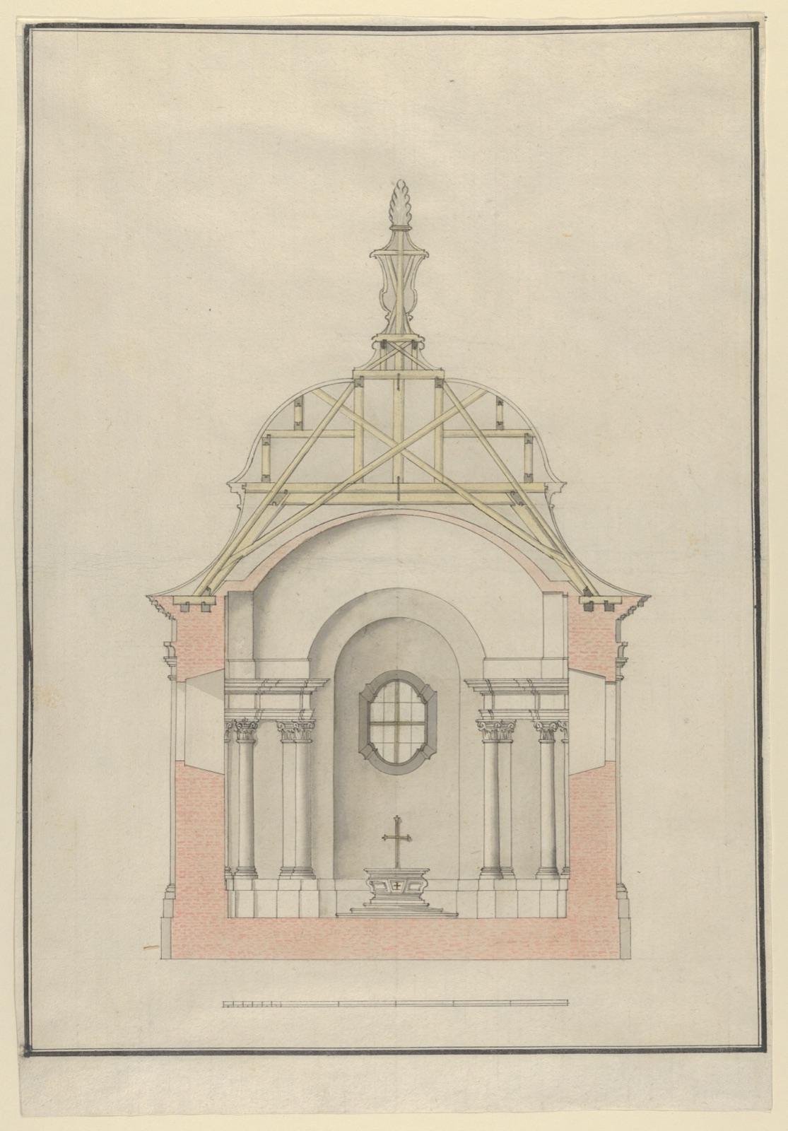
An anonymous seventeenth- or early-eighteenth-century Baroque chapel cross section in the Met makes the technical possibilities unusually visible. Its pinked cut walls show dense brickwork, while the roof outline exposes timber members above the inner vault; a scale lies below. The chapel's altar, composite columns and crowning vase appear in the same drawing. The museum describes construction clearly, but names no securely executed church. This is a cut through a scheme whose material and spatial claims can be analysed, not an as-built record merely because its masonry is meticulously rendered. The sheet also demonstrates that the section can combine a strong wall cut with an interior view and a roof profile rather than treating these as separate realms. [8]
HABS takes a different graphic decision for its standard measured drawings: its current guidance states that no poché should be shown in walls and floors cut in vertical section. It nevertheless asks surveyors to select informative cuts, tie their vertical measurement strings to an exterior horizontal datum, and record background features through openings. The no-poché clause is easy to misuse. It says something precise about a contemporary American heritage-documentation convention; it does not erase the coloured cuts in the older Met chapel drawing, the pink fields on Isaac Ware's Houghton Hall sheet or the expressive washes in an academic French projet. [1], [8], [11], [13]
The measured drawing also does not automatically reveal materials hidden behind plaster. A visible line may record the edge of a finished wall, but the joist system or earlier blocked opening behind it requires independent evidence. Photogrammetry can help establish present geometry on accessible surfaces; measured sketches, photographs, documentary research or targeted investigation may be required for the fabric a camera and tape cannot see. Such supplementary evidence changes the confidence of a section rather than making the section less important. [1], [3], [24], [31]

Text alternative for the diagram
Invented red wall/floor is intersected; teal surfaces are beyond. HABS no-poché in vertical cuts is a programme-specific convention.
The section as an interior sequence: house, theatre and hall
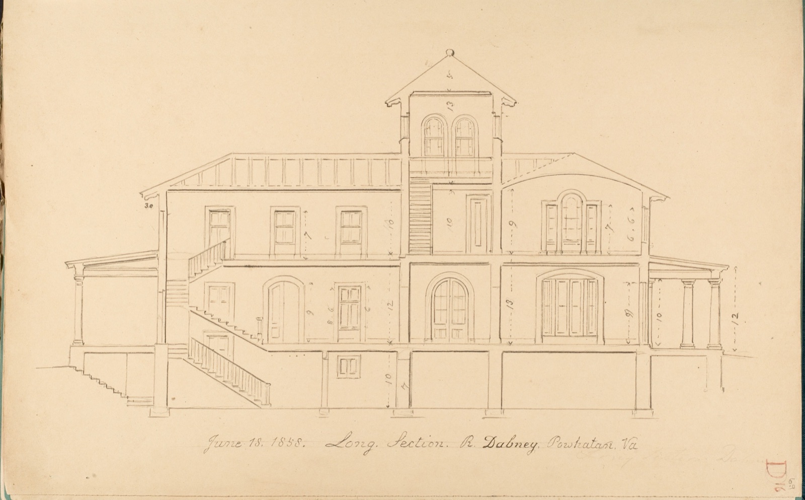
A long section can turn a floor-plan arrangement into a sequence of lived heights. Alexander Jackson Davis's signed Long Section for R. Dabney's house in Powhatan, Virginia, dated 18 June 1858, places a stair, rooms on differing levels, a central tower and a roof line in one broad horizontal sheet. Its drawn stair shows how arrival on one floor connects to another; floor-to-floor measurements appear beside the voids. The Met catalogue identifies maker, client/location and date, while the sheet visibly signs the long section. That evidence does not certify every room was eventually built at those dimensions, but it gives an unusually specific document to compare with any later building or related commission records. [9]
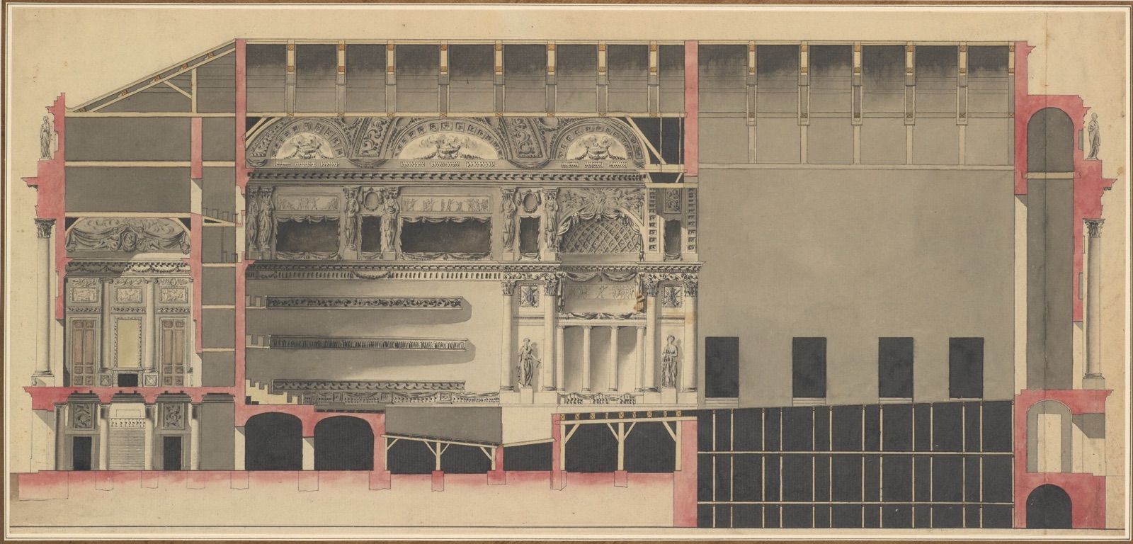
The long section of a theatre by Nicolas Marie Potain addresses another problem: stages, audience seating, box levels, roof space and the relation of performance to spectators. Its eighteenth-century washes mark thick construction and a decorated interior; the scale and cut distinguish the larger assembly from features in the auditorium. The Met's object record does not name a particular executed theatre. It is therefore strong evidence for a theatre design conception, not a claim that an anonymous building served audiences exactly this way. The paper makes an architectural point that a theatre front cannot: performing space and audience space must be aligned, and their levels, sightlines and supports are designed together. [10]
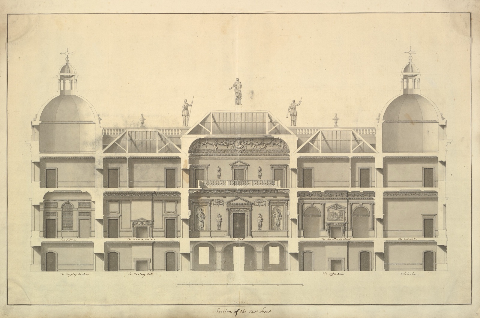
Isaac Ware's 1735 Houghton Hall east-front section has a different documentary status. The museum explicitly relates it to Ware and Thomas Ripley's published Plans, Elevations and Sections, Chimney-pieces and Ceilings of Houghton in Norfolk. Roof timbers, room floors, a central entrance composition and flanking domed forms sit in one long cut; some volumes are shown largely as outlines while other spaces have ornamental finish. Publication is part of its meaning. The sheet prepares a patron's house to be read as an ordered ensemble of rooms and faces, yet what its wash, selective interior decoration and print-making context convey need not equal a modern destructive investigation of every beam. [11]
The Met's anonymously attributed British drawing titled Vertical Section of a Four-Story House with Greek Wall Ornament illustrates an archival complication. Its colourful front-like presentation is dominated by rows of openings and wall decoration, with a lower dashed band; the catalogue calls it a section. The safest reading is to preserve the institution's title and describe what is visible, while not pretending that a reader can measure internal stair treads or floor assemblies from the photograph. A museum label is indispensable provenance, but its technical term should be interpreted against the marks rather than treated as a guarantee of any one graphic convention. [27]
Renaissance copies, Palladio's half views and the printed cut
The history of the orthographic section is neither a single inventor's moment nor a straight line from rough sketch to modern CAD. Cara Paul Rachele's Harvard doctoral abstract identifies Renaissance architectural copybooks as evidence for the empirical development of orthographic section drawing. Copying and sheet-to-sheet transmission matter: an architectural method is learned, adapted and remade in the act of drawing. The abstract does not establish a first folio or invention date. Other plate studies give firmer examples of how cut views work in a publication. [7]
Surviving medieval architectural sheets further complicate any story of sudden invention. The Met's Gothic by Design brings together plans, wall fronts, tower and vault studies, component drawings and cut views from different European collections. A partial drawing of a portal or vault was enough to solve some construction questions without representing every part of a cathedral. The surviving corpus reflects what workshops, patrons and archives retained; it cannot establish that a complete plan–elevation–section set was always required, or that section drawing began only when such a set first survives. [18]
In Andrea Palladio's I Quattro Libri dell'Architettura, half of an exterior elevation can be coupled with half of an interior section. Symmetry lets the reader imagine both halves as a complete building while comparing an outside cornice or roof profile with an inner height. Lorena Cristina Valdivia Steel's TU Berlin dissertation examines the graphic corpus and counts fourteen coupled half-elevation/half-section views among eighty-six analysed published objects; only seven fulfil the stricter same-sheet and same-scale relation she tests. Some views change orientation, scale or page arrangement. The pairing is a method selected for some objects, not a template imposed upon every Palladian building. [5]

Text alternative for the diagram
Invented half exterior and half interior align a floor and opening around a central line; no original Palladio plate is reproduced.
The printed page is itself architectural evidence. Half views on opposite sides of a leaf or on facing pages cannot be compared by casual digital cropping as if they were a single continuous projection. The book reader may have to turn a page or rotate a plan, and later reproductions may alter that experience. What seems to be an elegant alignment of exterior and interior can be a publishing choice as well as a geometric one. A modern caption should distinguish original drawing, engraved plate, edition and digitised photograph rather than quietly collapsing them. [5]
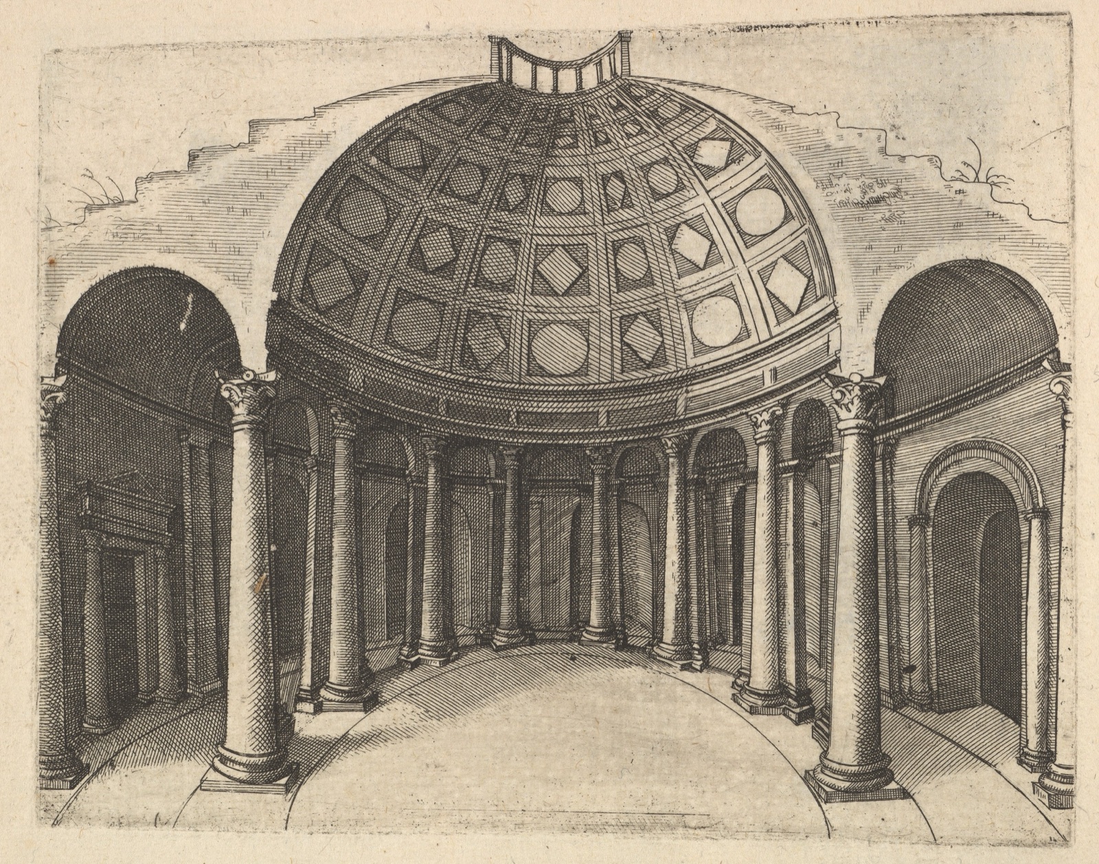
Lambert Suavius's 1554 etching of a round classical temple shows why the word cross-section cannot be equated with one orthographic graphic type. The printed view opens a domed interior but uses recession, shadow and dramatic depth to make that interior vivid. The Met notes that images in this series copied earlier Italian architectural prints, and that some pictured ancient buildings were artificially reconstructed from medieval descriptions whereas others were shown ruinous. A plate like this is a witness to Renaissance print culture and interpretation of antiquity. It is not a tape-measured vertical record of an intact Roman temple, and its partly reconstructed status must remain attached to the picture. [12]
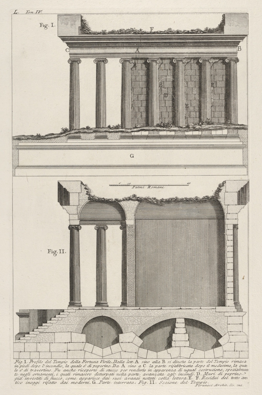
Piranesi's 1756 Profilo del Tempio della Fortuna Virile places a temple profile and a lower sectional treatment together in a different printed form. The drawn masonry, dark recesses and lettered parts argue about Roman construction and surviving fabric through selective representation. Such a plate can communicate an antiquarian hypothesis or measured-looking observation without granting every concealed void equal certainty. The history of a section includes its public audience and polemical purpose as well as its geometry. [17]
San Firenze: sections as proposed changes, not neutral companions
The Oratorian church project at San Firenze makes the section's design agency unusually clear. A 2022 Italian-language Uffizi study works across drawings of Pietro da Cortona and Pier Francesco Silvani, archival correspondence, accounts and a surviving wooden model. The authors count forty-one GDSU project drawings: eleven plans, twenty longitudinal sections, three transverse sections, six section details and one façade view. The drawings are not all dated or metrically labelled. Some plans are probably lost; some changes were made directly in a section, yielding intermediate cuts that no surviving plan exactly matches. A historian who paired every section mechanically with the nearest-looking plan would turn evidence of revision into a false completed set. [6]
Silvani's 1658–66 work initially attempted to reduce elements of Cortona's project to control cost, including the scale of freestanding columns, while keeping the possibility of completion alive. Correspondence and payment records show the negotiation: a 1660 payment mentions both variants of Cortona's plan and the interior façade of the original and moderated scheme. Cortona criticised how reducing pier and column dimensions changed the ratio between nave piers and chapel openings. The later scholars identify refined, watercoloured longitudinal and transverse sections—GDSU 2239 A, 2246 A, 2247 A, 2244 A and 2245 A—whose chapel openings correspond to that design dispute; they judge 2244 A, 2246 A and 2247 A to form a project group without an identified matching plan. These are architectural sections carrying decisions about proportions and spaces, not just drawings for an archive. [6]

Text alternative for the diagram
Three invented document states distinguish plan A, section B with a changed pier and model C. The graphic does not reconstruct San Firenze.
The study's plate of Silvani proposals visualises what the count alone cannot. Two longitudinal sections, a transverse section and a plan are reproduced at the same moment of the article; the high central volume and side aisles differ depending on the direction of the cut. The picture captions date the selected drawings to about 1660, identify GDSU 2257 A, 2260 A, 2261 A and 2259 A, and specify pen, wash and paper sizes. These are separate paper objects, even when a scholarly layout places them together. Their large size and colour matter: the interior was debated in drawings at a scale that could make relationships visible to patrons, not merely as a small part of a final façade plate. [6]
After a Rome stay in 1667, Silvani developed a later project that the authors say was realised only in part. A plan GDSU 2225 A and section GDSU 2229 A almost correspond to the surviving model; “almost” is important. A drawing-to-model match establishes one proposed design phase, not construction of every wall represented. The comparison also shows why one section could be more informative than the sole façade: internal height, nave rhythm, dome and chapel proportions were where the architectural and financial argument occurred. [6]
Academic projects, interiors and the persuasive slice
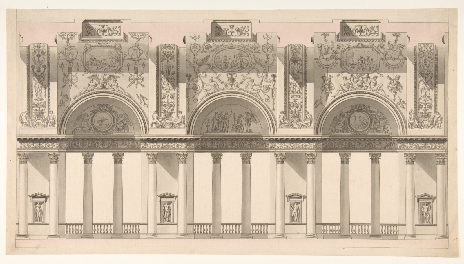
In late eighteenth-century France a highly finished section could demonstrate an architect's imagination and training. Charles Pierre Joseph Normand's Galerie dans le palais d'un souverain, dated by the Met to about 1791, uses grey and pink washes and rich ornament. The Met describes this class of drawing as projets made in academic or competition settings, many never realised, whose monumental schemes established designers' reputations. The pictured Normand sheet reads strongly as an ordered interior wall, a reminder that historical catalogue “section” can include the seen face beyond the cut, not always a graphic excavation of masonry. Its expensive-looking decorations are a design proposal. A palace gallery cannot be assigned to an executed sovereign's residence because the drawing is so convincing. [13]
Another anonymous eighteenth-century French sheet, catalogued by the Met as a Section of a Ballroom, concentrates on three doorways framed between pairs of columns beneath a broad coved upper form. What the photograph makes easiest to see is room-wall composition rather than a series of structural levels. It belongs beside a plan or a named commission if one wants to know how the room connected to a building, but the museum gives no secure realised site. Similarly Jean Jacques Lequeu's 1785–86 Hôtel de Montholon sheet has a title naming a small dining-room section and plan while the museum's accompanying prose refers to an antechamber wall elevation and plan. The two room names cannot be treated as identical without resolving the catalogue discrepancy. A section can be an interior design document whose catalogue terms and visible marks require careful separation. [26], [28]
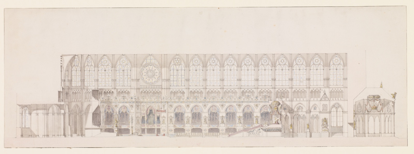
The Met's cross section of Reims Cathedral for the planned coronation of Louis XVIII adds an explicit political test. Charles Percier and Pierre François Léonard Fontaine drew the 1815 sheet with coloured ceremonial decoration in the cathedral nave. The Met says it is one of six drawings documenting plans for a coronation that never took place. Thus the section displays how decoration might have occupied a famous existing church, not what an audience actually saw on that unheld occasion. Site existence, design execution and event occurrence are three independent statuses. Its lengthy drawn nave and fittings stage the project for patrons and officials; a precise cross section cannot bridge the unexecuted event. [14]
The Politecnico di Milano's catalogue of Piero Bottoni's student work shows the long/short section distinction at the drawing-set level. For a 1924 academic palace for a musical association, it lists cuts AB, CD and EF at 1:100, a longitudinal section on a sheet 40.2 × 133.9 cm, front, rear and side elevations, plans and perspectives. The range indicates a designer testing separate journeys and volumes in a complex scheme. In other student house projects the same archive lists foundations at 1:20, roof details at 1:10 and window/carpentry construction at 1:10 alongside broader axis sections. These are records of architectural training, not evidence that the named palace or student houses were commissioned and built. Their different scales show why a grand spatial cut and a foundation detail answer different questions. [20]

Text alternative for the diagram
Two invented cuts compare broad space at 1:100 with foundation junction at 1:20, without claiming any exact Bottoni reconstruction.
Section, elevation and perspective can be deliberately combined
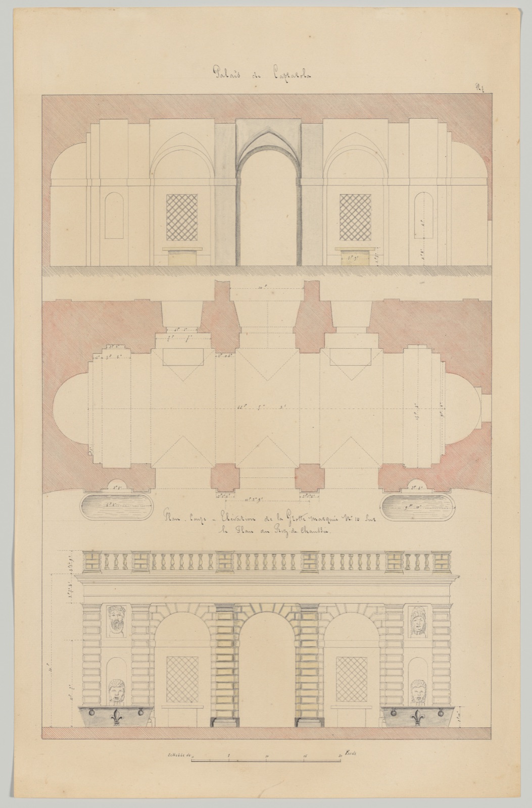
François Debret's 1815–23 study of a Caprarola garden grotto combines three views on one sheet: wall section, floor plan and frontal elevation. It was preparatory for a portfolio of Vignola's work rather than an original sixteenth-century design drawing by Vignola himself. Hatching had been planned for reproduction; watercolour and handwritten measurements were added. The plan locates projection, the section shows wall depth, and the elevation stages the face, yet the medium and date make it a later editorial interpretation of a historic building. Its “after Vignola” attribution names a design tradition, not the hand that made this particular study. [15]
In Eugène-Emmanuel Viollet-le-Duc's drawing of a Venetian palace, the section is perspectival. He opens several storeys to expose floor zones and roof construction while letting walls recede. The method can communicate the sense of inhabiting a building: rooms, balconies and stairs have a depth a flat orthographic projection cannot imitate. But one cannot transfer measurements across a perspective as if each horizontal edge were the same scale. The Met's dating is broad, 1830–79, and its architectural description does not certify a measured visit to a named surviving palace. The cut is historically useful as an argument about layered Venetian space, not a trustworthy dimensional survey. [16]
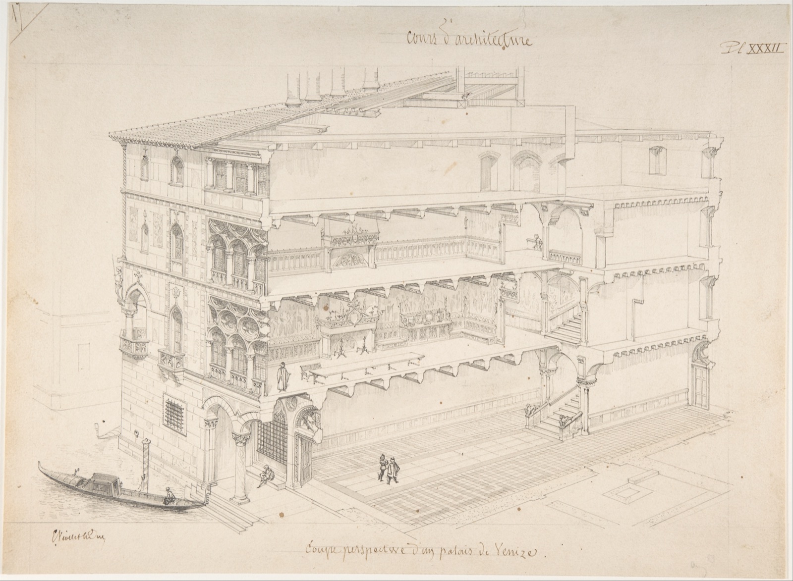
Perspectival cross sections, sectioned axonometrics and orthogonal cuts all reveal by removing a part of the represented envelope. They do not share a single mathematical promise. A perspective can emphasise movement and give a reader an immediate spatial intuition, while an orthographic section more easily aligns levels and proportional heights. An axonometric cut keeps parallel axes but lets multiple surfaces enter the picture. Combining methods can be an honest architectural decision; calling all of them “an accurate section” without qualification erases their intended tasks. Alkan's thesis explores precisely how standard plan–elevation–section sets may become less economical when a building departs from symmetrical, frontal geometry. [2], [4], [16]
Modern complex geometry and multiple kinds of section
The Berlin Philharmonie, designed by Hans Scharoun and completed in 1963, challenged a tidy box of one plan, one front and one axial section. Alkan's thesis, drawing explicitly on Robin Evans, describes how Scharoun and associate Werner Weber worked through sketches and models but found the standard drawing set inadequate when construction began. The foundations acquired errors, and close-spaced, large-scale sections were then used to make irregular geometry more surveyable for builders. Alkan's account is a theoretical interpretation of Evans, not a complete schedule of original construction sheets. It nevertheless illustrates a general point: a single section showing the whole deep auditorium could be too saturated with elements behind the cut, while many near-profile cuts could convey enough local shape to build. [4]
At Yokohama there is a second, more directly catalogued complexity. The CCA's Foreign Office Architects fonds lists a technical drawing book for the Yokohama International Ferry Port Terminal with a March 2000 longitudinal section, number 3-1020, plus detail sections 3-1105 and separate drainage-system sections 3-1417. Plans, elevation and roof plan sit in the same series; the records name English and Japanese as sheet languages. The archive makes visible the separation of spatial section, structural junction and service-system cut. A roof-as-landscape proposal needs a long sweep to communicate its public form, but a drain crossing or ramp detail requires a more local answer. [21]
Another CCA Yokohama section belongs to Peter Eisenman Architects' 1994 competition submission, not the FOA technical set. The Eisenman project file describes 171 drawings and labels the submission unexecuted. A catalogue search for “Yokohama section” can therefore deliver drawings for two architects and two very different project statuses. The section image alone cannot identify the built terminal. A careful comparison should name architect, phase, original archive, year, and whether the project went forward before inferring what a cut says about the realised port. [22]
In Japanese historical drawing archives the vocabulary and collection structure differ again. Kyoto University's catalogue for Josiah Conder's Furukawa residence lists 58 manuscript sheets. Its entries include sections on sheets 349 and 350, a whole wall/roof 矩計 sheet 358, and balcony, porch and greenhouse details combining plan, elevation and section. The word 矩計 conveys a construction-focused vertical cut through building assembly, not merely a picturesque interior face. The archive catalogue gives huge B1/A0 sheets and individual list numbers, but the digitised publication year is not the year each design drawing was made. The Japanese records prove why a sections history limited to European print plates would miss important evidence of building assembly and archival organisation. [19]
The UPM doctoral abstract on Enric Miralles supplies a more cautious interpretive counterpoint. It identifies layered plans and partial sections as parts of a twentieth-century architect's working language rather than treating the three orthographic views as neutral boxes. That summary does not define every drawing in Miralles's archive. It does guard against a false assumption that every complex form can be completely or economically generated from one conventional section. Multiple scales, partial cuts, models and other projected views can form a design language together. [32]
The later measured section and hidden fabric
A section drawn after a building is a dated witness to existing condition, not an original designer's intention. UPM's Spanish historic-building survey discussion uses sección for vertical or three-dimensional cut views and insists that measured drawings be read with photographs and prior documentation. HABS asks surveyors to measure through floor openings where possible, establish a horizontal datum and record features that would be seen beyond the plane. Those practices give a later section demonstrable locations and levels. They cannot turn a concealed roof truss into observed fact by graphic confidence alone. [1], [3]

Text alternative for the diagram
Three document boxes identify proposal, possibly changed building and dated as-found survey; no inevitable sequence for every site is claimed.
The Fort McHenry powder magazine gives a striking documented example. The Library of Congress HABS history records that Captain Thompson sent a plan and section on 24 June 1839 while assessing whether the roof could be lowered. His drawing was generally correct but contained assumptions about vent holes and the roof frame. A follow-up letter admitted error: a person sent into the space under the roof could not see enough in the darkness, and Thompson concluded the structure could only truly be seen with the roof off. The magazine had a brick vault beneath a separate roof superstructure, precisely the relationship a useful section ought to display. Yet an inaccessible cavity forced inference. The surviving history preserves both the drawing's date and its uncertainty, allowing later observed evidence to test it. [24]

Conservation sections can do work still further from the original design sheet. A 2025 Spanish research paper by Milagros Palma Crespo and colleagues recommends sections and construction details through important junctions—ground/foundation, floor crossings and roof contacts—before mapping damage in historic masonry. It also describes phases and materials represented across plan, section and elevation, so that cracks or other lesions can be related to structural systems and later alterations. Such a drawing is partly a diagnosis: it locates observed damage and interprets building phases. Its coloured or hatched phase map does not mean the original architect designed those divisions, and a section without material examination cannot independently settle the cause of each fissure. [23]
The restored Amiriya Madrasa at Rada'a, Yemen, is a useful reminder of why vertical reading matters outside European house and church types. The Aga Khan Trust for Culture's Archnet record describes a three-storey fifteenth-century complex: ground-floor shops and vaulted rooms, a first-floor prayer hall, stairs from porches, a roof terrace, clerestory light and six domes. Restoration between 1982 and 2004 rebuilt or repaired limestone, baked brick, qudad waterproofing and decorated interiors. To comprehend the relation of commercial ground floor, court, prayer hall and roof light requires vertical questions, not only the ground plan. The archive groups restoration drawings but its overview does not identify an individual vertical section; the building's recorded spatial relationships support the argument without assigning them to an unspecified sheet. [25]
What a section can prove—and what it cannot
A good section gives a reader a powerful account of how one selected slice relates level, space and fabric. It can reveal a stair as a journey rather than a symbol on a plan; a theatre as a relationship between stage and audience; a chapel roof as a physical assembly over an interior vault. Sections can also persuade a client, present an academic competition, publish a historic building, guide construction or map later damage. In each case the cut plane and sheet status govern its evidentiary reach. The maker's date is not necessarily the building's date; a measured survey need not be the designer's scheme; a labelled “section” may show a decorative interior face; a printed antique temple might combine ruin and conjecture. [1], [2], [3], [4], [6], [8], [9], [10], [11], [12], [13], [14], [15], [16], [17], [20], [21], [22], [23], [24], [25]
The most reliable way to read a section is to triangulate it. Locate the cut on a plan and check its looking direction. Compare the visible exterior with an elevation, and the claimed thickness or junction with details, photographs or material investigation. Identify the drawing's maker, inscription, date, medium, scale, repository and original purpose. Ask whether the sheet belongs to a proposal, revision, built work, copy, print, academic exercise or later survey. Only then can the remarkable density of a cut be used without making it claim more than its record supports. [1], [3], [5], [6], [15], [19], [20], [21], [22], [23], [24], [29], [31]
Explore RELATED Artworks and Records
Historic catalogues use the word section for more than one kind of interior image.
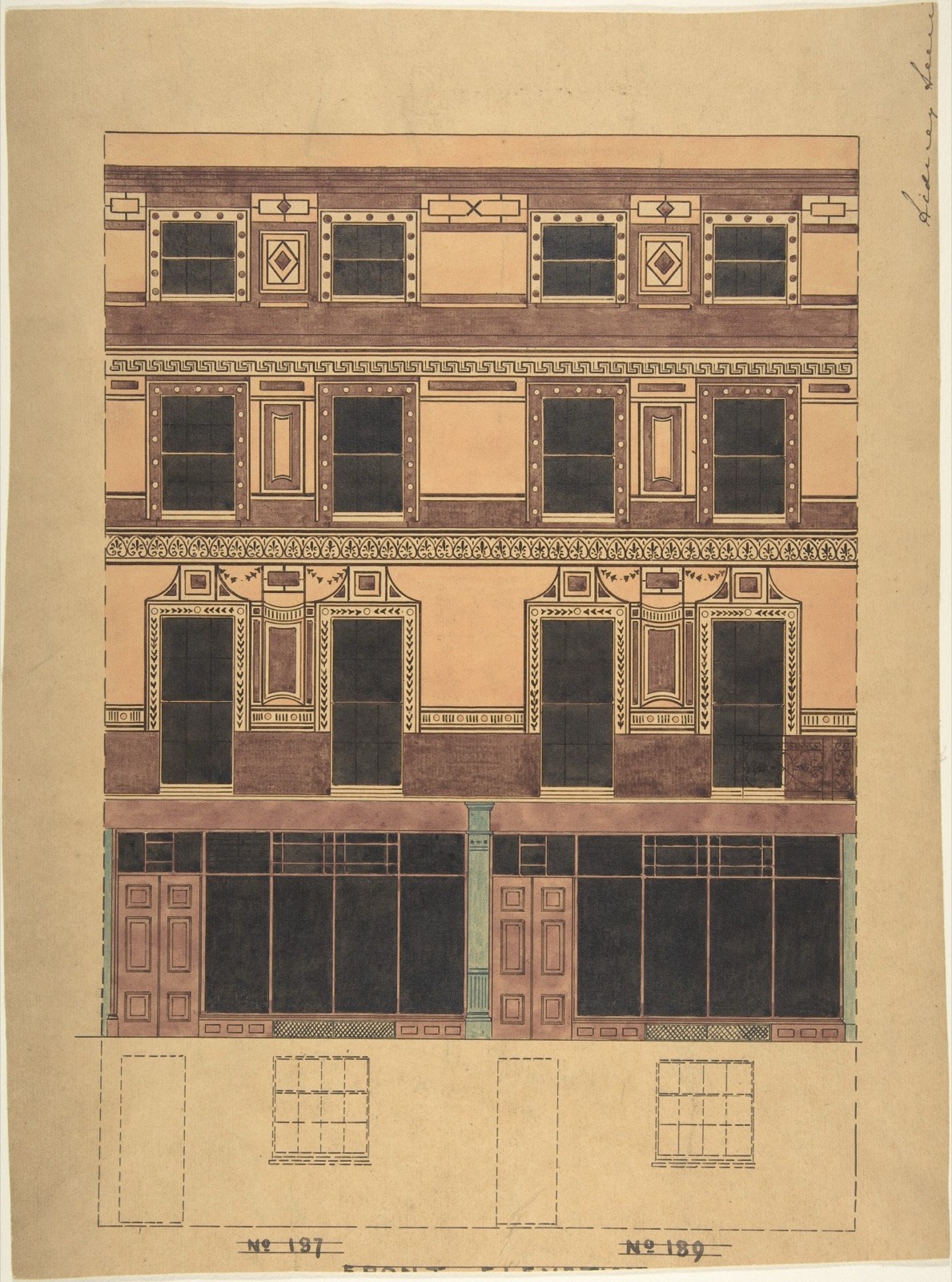
A four-storey “section”
Frontal ornament versus catalogue cut vocabulary.
The Met · public-domain drawing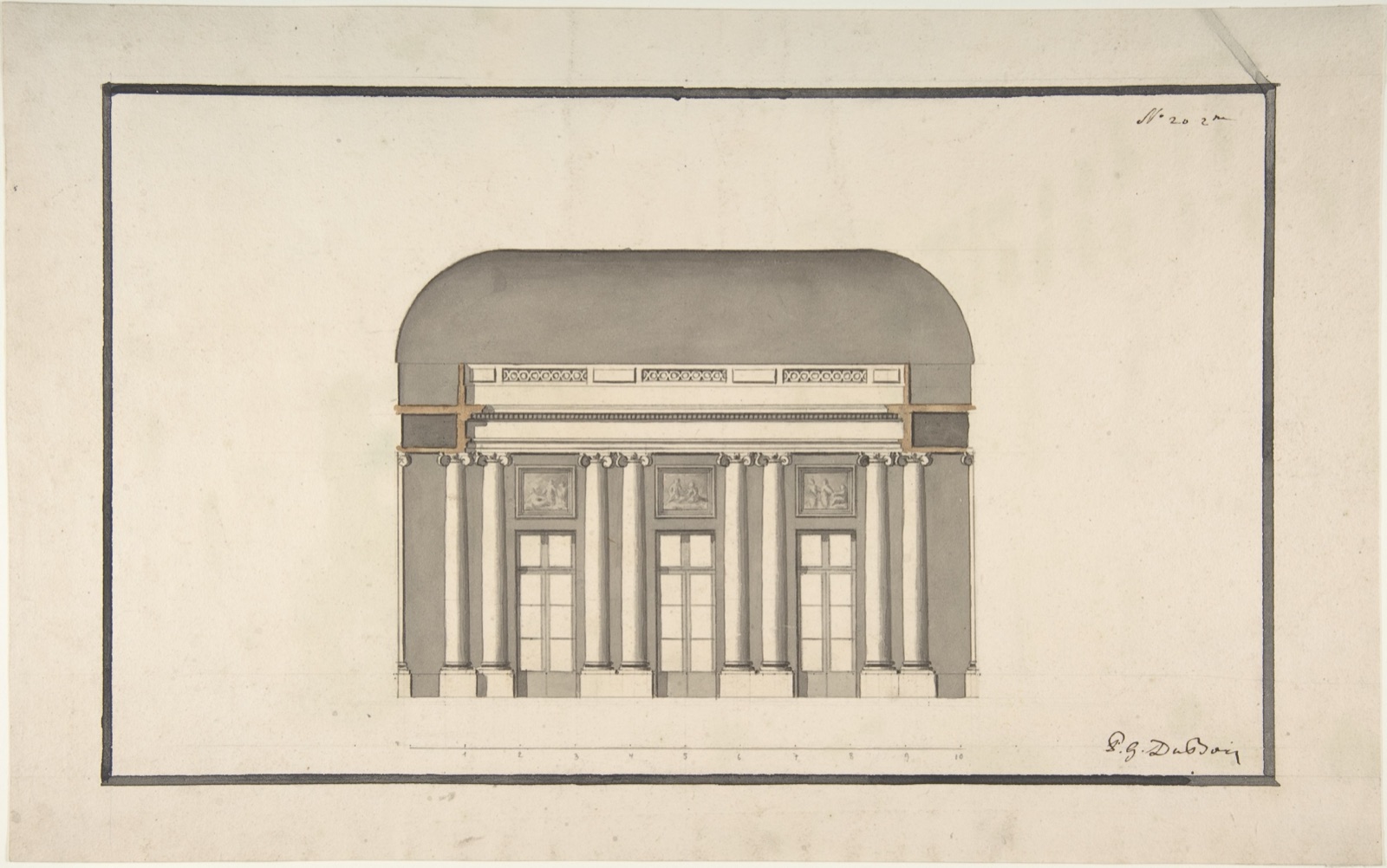
A ballroom “section”
Room-wall arrangement in a French drawing.
The Met · public-domain drawing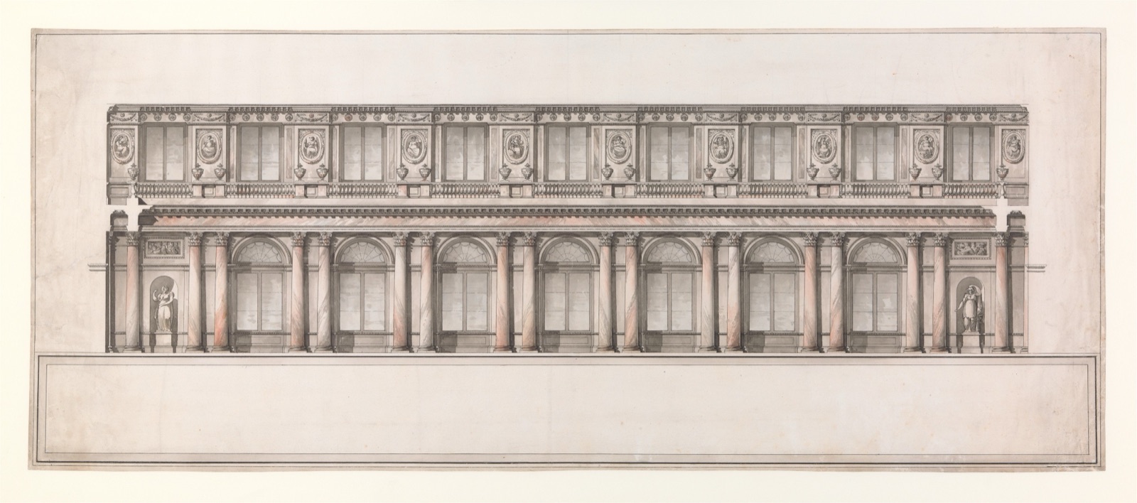
Saint George’s Hall
A Quarenghi-attributed long interior view.
The Met · public-domain drawing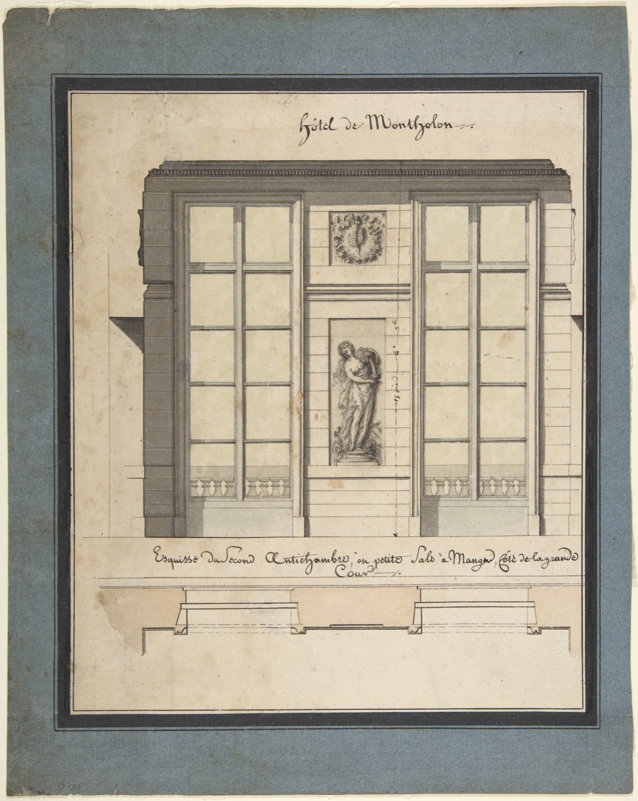
Hôtel de Montholon
Lequeu combines a room wall and plan.
The Met · public-domain drawingWatch: Architectural Drawing and Space
Institutional films on historic drawing geometry and physical sheets.
Reconstructing a Gothic Vault Design
A modern exploration of spatial construction from a medieval design sheet.
Original illustrated preview, not a film still.
Learning from Roriczer’s Pinnacle
Plan geometry carried upward into a vertical architectural form.
Original illustrated preview, not a film still.
Conserving Michelangelo
Conservation makes the material and marks of an architectural drawing visible.
Original illustrated preview, not a film still.Frequently Asked Questions
No. It is a selected, constructed drawing whose cut plane and view beyond it must be interpreted. [1] [4]
One generally follows a principal length and the other crosses it; the actual cut must still be located on a plan. [1] [6]
Yes. Academic projets, competition submissions and ceremonial schemes can all be precise sections without execution. [13] [14] [20] [22]
No. Conventions differ; current HABS guidance specifically omits poché in walls and floors cut in vertical section. [1] [8] [11]
A METU thesis reports that irregular geometry required close-spaced, large-scale sections when conventional views became hard to build from. [4]
Not automatically. Fort McHenry’s 1839 roof section included acknowledged assumptions where a cavity could not be seen. [24]
References
- National Park Service, HABS Guidelines: Measured Drawings, §§3.5, 4.7, 5.2.
- Universidad Politécnica de Madrid, Osanz Díaz et al., CAD and systems of building representation, 2010.
- UPM, Valiente, Levantamiento de planos, 2006.
- Middle East Technical University, Alper Semih Alkan, Framing the Invisible: “Section” as a Spatial Frame, 2004.
- Technische Universität Berlin, Lorena Cristina Valdivia Steel, Palladio orthogonal drawing thesis, 2018.
- Gallerie degli Uffizi, Imagines 6, San Firenze article, 2022.
- Harvard DASH, Cara Paul Rachele, Building Through the Paper, doctoral dissertation abstract, 2015.
- The Met, anonymous Baroque chapel cross section, object 399777.
- The Met, Alexander Jackson Davis, R. Dabney house long section, object 394195.
- The Met, Nicolas Marie Potain, theatre longitudinal section, object 362067.
- The Met, Isaac Ware, east-front section of Houghton Hall, object 369731.
- The Met, Lambert Suavius, printed cross section of a round temple, object 408629.
- The Met, Charles Pierre Joseph Normand, sovereign's palace gallery projet, object 362248.
- The Met, Charles Percier and Pierre François Léonard Fontaine, Reims coronation section, object 362785.
- The Met, François Debret, Caprarola grotto multi-view study, object 714430.
- The Met, Eugène-Emmanuel Viollet-le-Duc, Venetian palace perspectival section, object 343315.
- The Met, Giovanni Battista Piranesi, Temple of Fortuna Virilis profile and section, object 416056.
- The Met, Gothic by Design: The Dawn of Architectural Draftsmanship.
- Kyoto University rare materials digital archive, Josiah Conder's Furukawa residence drawing corpus.
- Politecnico di Milano, Archivio Piero Bottoni, Elaborati accademici (1921–1926).
- Canadian Centre for Architecture, Foreign Office Architects fonds, Yokohama technical drawing series.
- CCA, Peter Eisenman fonds, unexecuted Yokohama International Port Terminal competition submission.
- M. Palma Crespo et al., Hacia una normalización del sistema de cartografiado de lesiones en fábricas históricas, 2025.
- Library of Congress, HABS MD-197, Fort McHenry powder magazine history.
- Aga Khan Trust for Culture / Archnet, Amiriya Madrasa Restoration, Rada'a.
- The Met, Jean Jacques Lequeu, Hôtel de Montholon section/plan, object 335833.
- The Met, anonymous British four-storey house “vertical section”, object 364345.
- The Met, anonymous French ballroom “section”, object 343674.
- RIBA Collections, catalogues to the drawings collection.
- The Met, Open Access policy and collection API.
- Historic England, Photogrammetric Applications for Cultural Heritage.
- UPM, La planta Miralles, doctoral abstract.
- The Met, attributed Giacomo Quarenghi, Saint George's Hall longitudinal section, object 346111.
Explore RELATED Architecture
These built-place pages show why plans, perspective, photographs and later records must be read together.
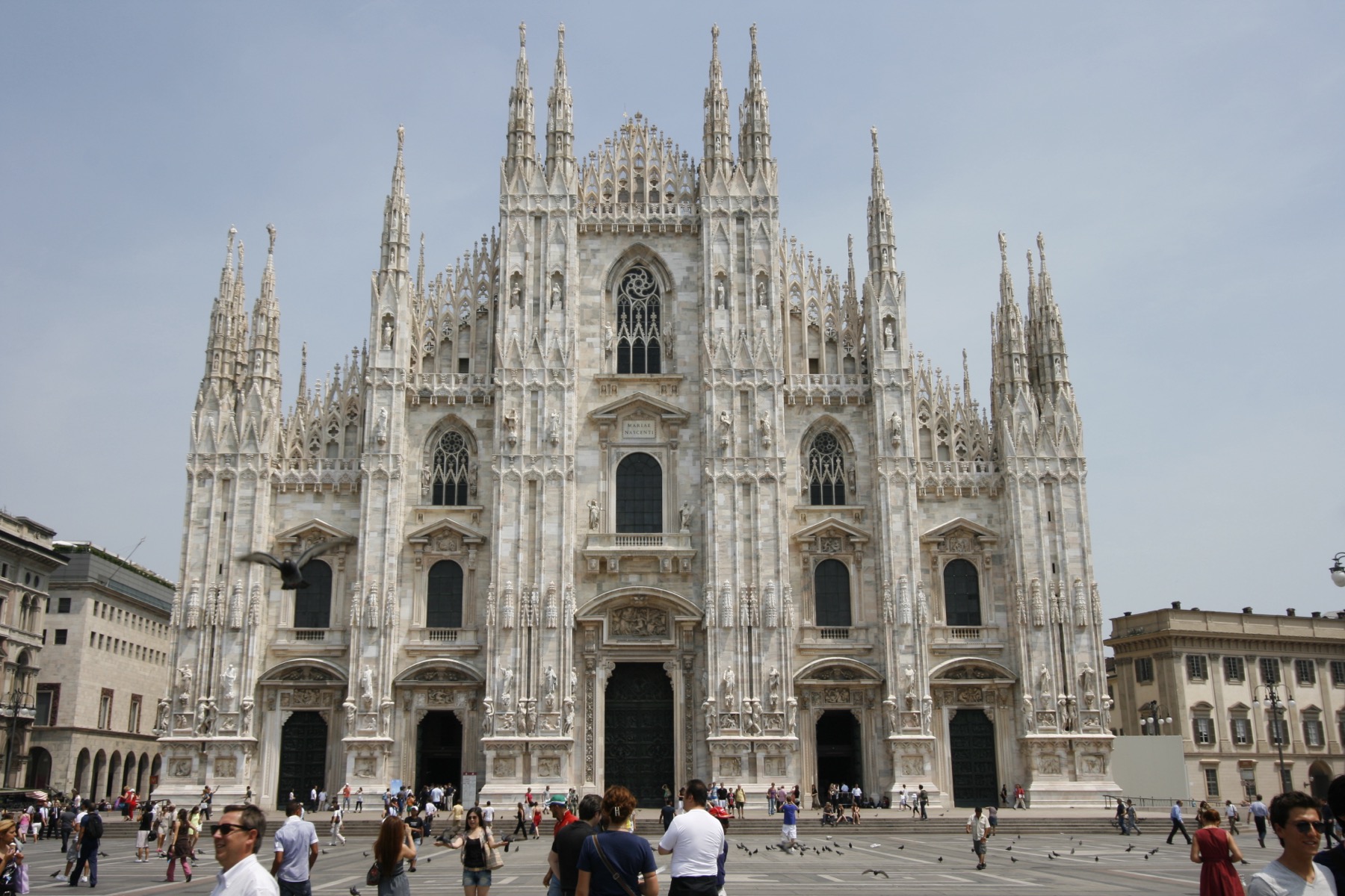
Milan Cathedral
Design and geometry changed through argument and building.
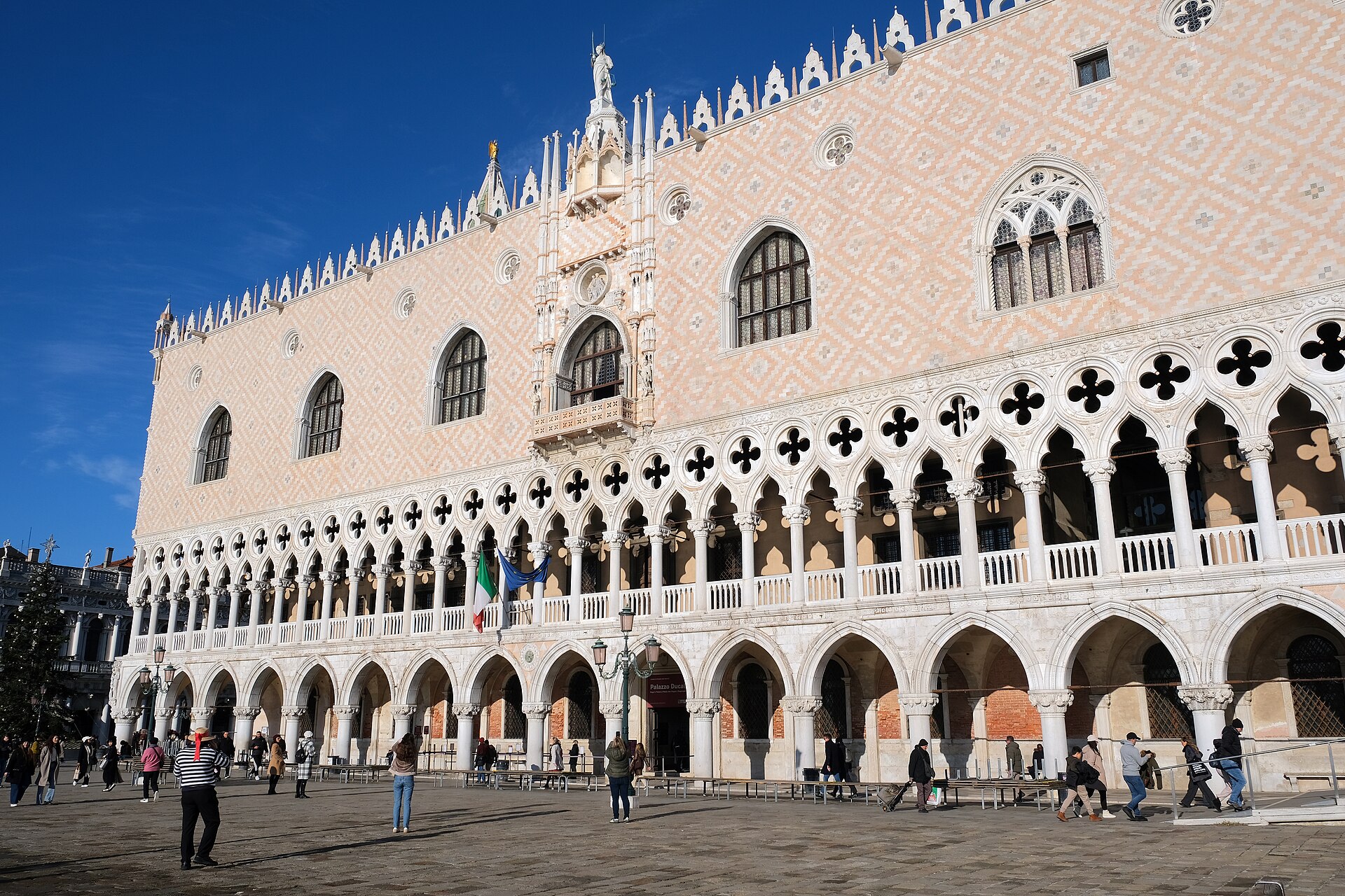
Doge's Palace
A facade conceals a long sequence of alterations and uses.
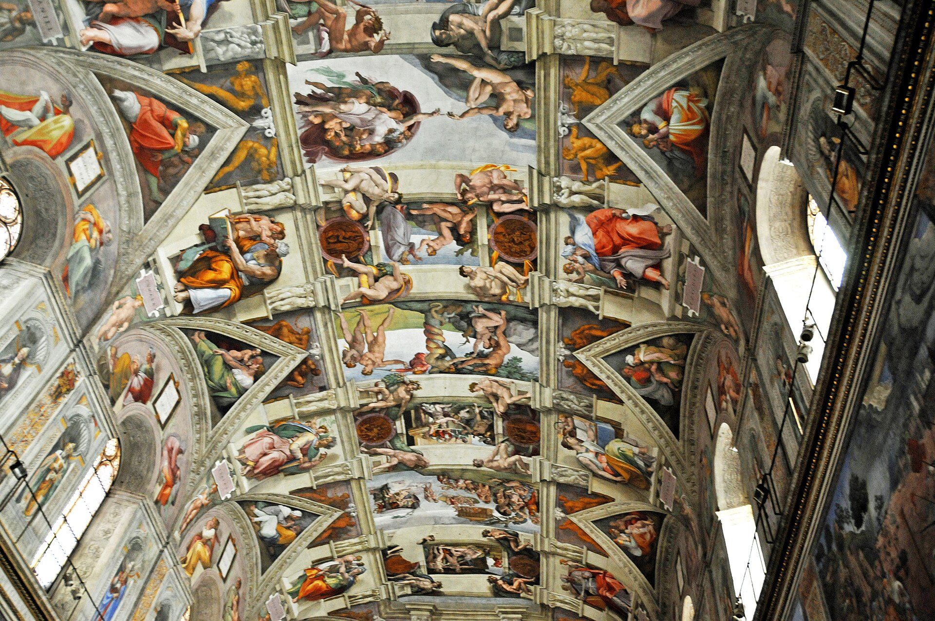
Sistine Chapel
Architectural fabric and painted programmes have different records.

Borobudur
Plan and visitor sequence reveal different spatial relations.

Machu Picchu
Ruins and later surveys mediate the reading of built terraces.
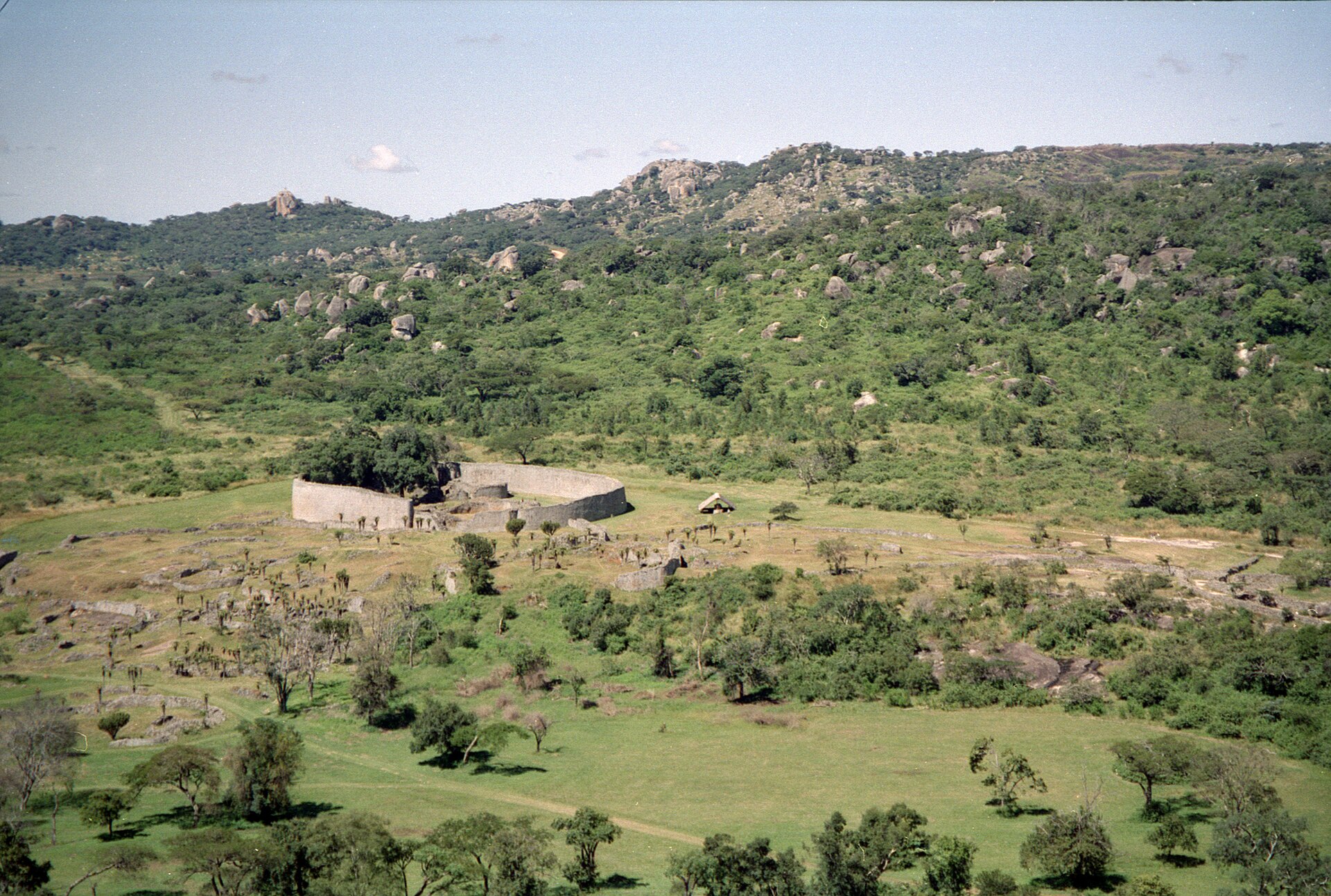
Great Zimbabwe
Heritage records must distinguish fabric from later inference.
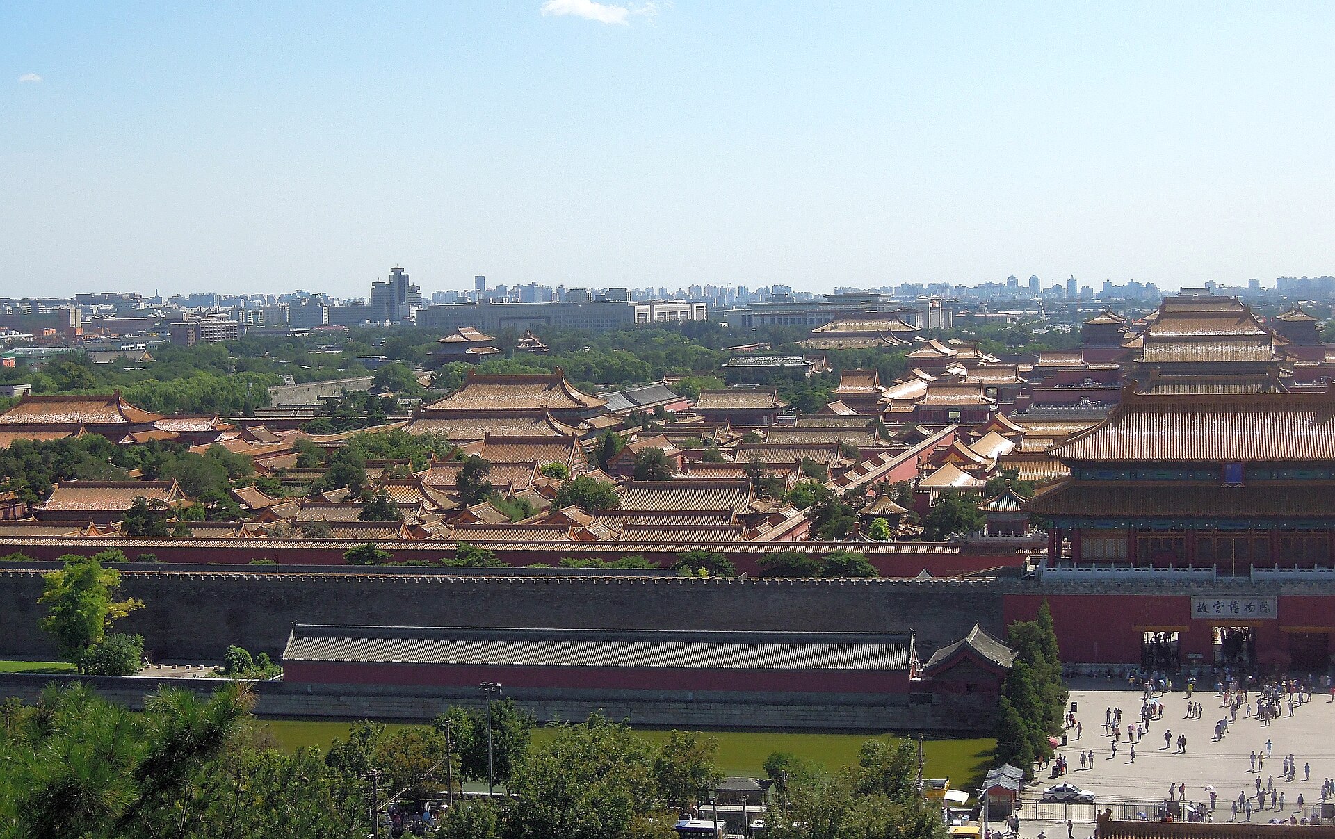
Forbidden City
Palace plans and surviving courts changed across reigns.

Teotihuacan
Archaeological plan and exposed monuments are not the whole city.