


 by Tom Gurney
Tom Gurney BSc (Hons) is an art history expert with over 20 years experience
Email: tomgurney1@gmail.com / Phone: +44 7429 011000
Drawing, Purpose and Historical Witness
An architectural drawing is not simply a picture of a building. It may be a quick investigation, a proposal put before a patron, a set of instructions shared among trades, an image prepared for publication, or a measured account of walls already standing. It can be copied, revised, bound into a book, or entered into an archive long after the work that prompted it. Two sheets that look equally authoritative may have opposite relationships to construction: one records an unbuilt design; the other depicts an altered building at the time of survey. The first questions are therefore what the sheet was meant to do, when it was made, and whose hand and information it contains. [1], [4], [5], [6], [10], [23]
Historic collections reveal the range. The Royal Institute of British Architects divides design drawings from topographical records of existing fabric, while acknowledging exploratory, presentation, working and specialist sheets within an estimated collection of around a million drawings. The Bibliothèque nationale de France preserves croquis, esquisses, plans, surveys and printed images; Kyoto University keeps Edo-period palace drawings that can fold into spatial objects. None of these holdings is a complete census of how everyone built. Each is a historically shaped survival of sheets, copies and decisions. Their variety makes “drawing” a useful broad word only if we keep its different jobs in view. [1], [4], [12], [18], [19]
At a Glance
- First questionProposal, instruction, publication, copy, survey or reconstruction? [1], [23]
- MakersArchitects, draughtspeople, surveyors and specialists may share a project. [1], [22]
- ViewsPlan: horizontal cut; elevation: projected face; section: vertical cut. [22]
- MaterialsGraphite, ink, wash, vellum, tracing paper and digital files. [1], [12]
- ReproductionEngraving, blueprint, diazo, photocopy and scan transform originals. [1], [10]
- HistoryGothic, Renaissance and Edo sheets served different practices. [6], [15], [18]
- HeritageA measured survey records condition at the survey date. [23]
- ReadingCheck maker, date, scale, legend, revision and source. [3], [22]
Contents
- Design, record, or something between
- Surviving medieval sheets and the work of geometry
- From survey mark to proposal on the Renaissance sheet
- What a change of pen or wash can tell us
- Printed drawings can change the original question
- Learning to read a plan, elevation and section sheet
- A set of drawings is a conversation among trades
- Drawings made after the building
- Original, copy, blueprint and scan
- A drawing as a historical witness
Design, record, or something between
RIBA’s distinction between design and topographical drawing is a powerful starting point. A design sheet may consider a building that was constructed, a rejected option, a student exercise, or an unsuccessful competition entry. A topographical sheet records what its maker saw or measured in an existing building or landscape; it may be a sketch, a formal survey, or a picturesque view. An architect can also sketch an ancient wall on one side of a sheet and try a solution for a new project on the other. The category of the archive is useful for finding material, but the marks on an individual sheet still determine what it can establish. [1], [2]
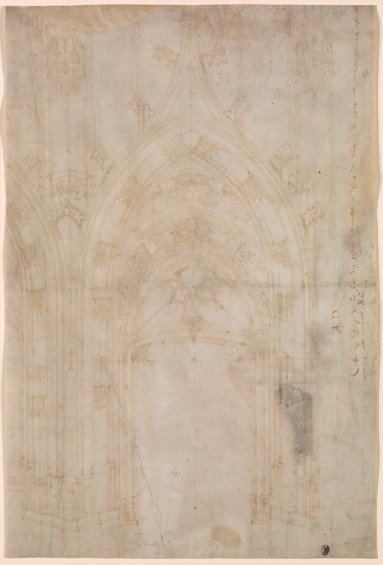
The date of drawing is not automatically the date of construction. A design might precede building by years; a copy may postdate the design; a survey may have been made after an addition changed the plan. A later historical reconstruction can show an inferred lost phase with crisp lines while remaining an argument about evidence rather than an observation. It is equally important not to assume that an architectural-looking image instructed anyone to build. The Met’s French vellum drawing of 1450–1500 resembles the west facade of Rouen’s Saint-Maclou, but the museum explicitly says there is no evidence that it served as the model for an existing building. Similarity makes an interesting comparison; it does not turn the sheet into a construction contract. [6], [7], [23], [24], [25], [26], [30]

Text alternative for the diagram
These four statuses are illustrative and can overlap on one project. The graphic is not an archive classification or a mandatory construction sequence.
The record also changes its audience. A rapid drawing can help a designer compare arrangements privately; a carefully washed elevation might convince a patron; a plotted roof profile can communicate a shape to an artisan; a keyed site survey can help a conservator distinguish stone observed from a proposed restoration. Finish is not a simple measure of usefulness. The task and the people relying on the sheet decide which information it needs. [1], [9], [10], [15], [16], [22], [23]
An archive can hold these different audiences side by side. The BnF’s Robert de Cotte inventory describes architectural and decorative drawings by an architect whose office addressed royal commissions. Its published catalogue description establishes the breadth of the fonds, but does not by itself establish the hand, date or construction status of any individual sheet: those claims require the individual record and, where possible, the object. The inventory is therefore a route into evidence, not a license to treat a whole office’s drawings as one finished design. [12], [13], [14]
Surviving medieval sheets and the work of geometry
Some large Gothic architectural drawings survive on parchment and paper, but survival cannot supply a firm invention date. The Metropolitan Museum notes that the earliest known examples are around 1250 and already sophisticated. Earlier work may have been discarded or its support reused after building. Workshop preservation subsequently made some Rhine and Danube projects unusually visible in the record, while others remain known mainly through fabric and later texts. A history drawn only from preserved sheets would mistake the habits of keeping and collecting for the whole history of making. [6]
Blindly scored guidelines, straightedges and compass arcs beneath ink lines disclose deliberate geometric work. Floor plans, vaulting plans, elevations and assembly diagrams carried different information to masons, carpenters and metalsmiths. A plan of a complex element might allow a maker to extrapolate a three-dimensional arrangement, but that inference relied on shared skill at the workshop and building site, not on the paper acting alone. The Met’s modern film about Matthes Roriczer’s 1486 booklet makes the plan-to-elevation logic visible by reconstructing a possible design in three dimensions. It demonstrates a historical method through current animation; it is not documentary footage of fifteenth-century work. [6], [29]

Text alternative for the diagram
The invented schematic separates geometric preparation from visible ink; no specific medieval vellum has been redrawn.
A small drawing of an architectural form was not necessarily a plan for a full building. The museum’s Gothic exhibition also shows plans and designs for liturgical metalwork and ornament, where the architectonic language of spires, portals and tracery moved between scales and trades. Some surviving workshop sheets are themselves later copies after other drawings. The act of tracing, copying or reducing an idea could be part of study and production, not merely a postscript to an original. The question remains specific: what object or building was the maker drawing, and for whom? [6]
From survey mark to proposal on the Renaissance sheet
Renaissance architectural sheets offer a different mixture of observation and invention. RIBA’s Palladio research account points to surveys of ancient fabric, first ideas, erased marks, smudges and paper overlays among sheets later prized by collectors. The traces are not embarrassing leftovers beneath an authoritative final line. They can show where an architect explored a form, reconsidered a dimension or brought evidence from an older building into a new proposal. A fully restored digital image may make the drawn architecture readable while obscuring the physical sequence of making; the recto, verso, fold, pasted addition and recorded provenance can matter as much as the selected front view. [2], [3]
Giovanni Antonio Dosio’s Uffizi sheet of the Temple of Antoninus and Faustina offers a particularly clear example of drawing as research. On one side he brought a plan together with measurements, architectural details and a transcribed inscription; on the other he drew an elevation and capital. The museum reads his refusal to fill gaps in the fragmentary monument as a philological choice. The sheet studies an existing Roman monument, not a new sixteenth-century commission and certainly not the Roman builders’ original plan. Dosio discussed a treatise in correspondence, but that book was not completed; the presence of a study drawing is not proof that every proposed publication occurred. [15]

Text alternative for the diagram
This is an invented relationship inspired by Renaissance research sheets, not a transcription of Dosio’s Uffizi object.
Other sheets could act for a patron or craftsman. Met curators describe Renaissance drawings that combine measured and suggestive information, making a project intelligible without pretending that the same view answers every construction question. Uffizi’s study of Florentine and Roman wooden ceilings describes a large orthogonal projection formed from two joined sheets. Its geometry helped artisans understand combinations of shapes in the ceiling; related technical, ornamental and figural drawings show that architecture met other arts at the point of execution. The drawing is not reducible to a pretty gallery image, but neither is its later display irrelevant to how we now learn from it. [8], [9], [16]
What a change of pen or wash can tell us
The University of York dissertation on Colen Campbell follows the same architect across differently purposed drawings. For London’s Rolls House, a surviving site plan measured the limits of a complicated plot and adjacent buildings. Its graphite and ink annotations and scale served an early understanding of the place. It did not need the visual finish of a presentation. A Goodwood House preliminary sheet set plan and elevation together, with graphite guidelines linking the views; lower parts were inked while other portions remained exploratory. In the scholar’s reading, this was a working stage in which alternatives were still being tested, not a drawing “unfinished” because the patron had not yet seen it. [10]
For a patron, Campbell could make a more polished ink-and-wash elevation with much of the underdrawing concealed. The impressive surface could help secure a commission. It should not be confused with a sheet that recorded all working dimensions or the final building’s every alteration. The surviving archive is itself partial: some groups of office drawings were lost or separated, and the York author marks uncertainties of attribution and provenance. This case therefore shows a range of purposes within one practice, not a rigid rule that all architects followed site plan, exploratory graphite, washed presentation and working set in that order. [10]
When Campbell prepared plates for Vitruvius Britannicus, another use altered the marks again. The engraver needed a drawing suited to cutting a copperplate; many preparations used scored underdrawing, ruled ink lines and indications of cast shadow. Campbell drew nearly all in reverse because the printed impression would reverse the copperplate. In some cases he redrew and resized material supplied by other architects or taken from existing engravings. York’s analysis argues that this publication was largely paper-to-paper and not the product of his systematically measuring every pictured building. The evidence varies by plate and surviving source, so the careful conclusion is not that every image is inaccurate. It is that a published image, its preparatory drawing, its borrowed source and an extant building have distinct histories. [10]

Text alternative for the diagram
Source sheet, engraved plate and printed impression are separate records and may also differ in scale and selection.
Printed drawings can change the original question
The architectural drawing may enter a book, periodical, exhibition or school long after a single client decision. A print can carry plan and elevation to someone who has never visited the site. It can also arrange plates into a sequence, revise their scale and omit the messy marks through which a design first emerged. A volume of illustrations argues through selection and order. Campbell’s engraver sheets demonstrate this materially; the relationship between drawn source and printed plate is an act of production, not a transparent transfer. [10]
Jurjen Zeinstra’s TU Delft dissertation traces a later, narrower case in German architectural magazines. Some of Heinrich Tessenow’s Gewünschte Skizzen—requested sketches—responded to readers’ specific questions and appeared beside a plan or section. The same perspective could reappear in another journal or Tessenow’s books without its initial question and sometimes under another title. Detached from the first assignment, it could become a more general discussion of housing, craft or spatial experience. Zeinstra’s study of drawings and texts shows that a drawing can initiate discourse rather than merely illustrate a paragraph. His iconographic interpretation concerns Tessenow’s early twentieth-century German corpus; it is not proof that every perspectival view is equally legible to all readers. [11]
Tessenow’s 1907 portfolio brought loose plates together, letting a reader physically compare one drawing with another rather than encounter them only in a fixed line of prose. Some plates depicted existing traditions and others new proposals without a prominent division. That format could encourage an argument about continuity, but it also makes later cataloguing difficult if the caption does not identify each plate’s status and initial source. A book may preserve a drawing beautifully and still change what it appears to say. [11]
The Politecnico di Milano’s Piero Bottoni archive gives a different example of drawings made for learning rather than for construction. It groups academic exercises from 1921–26 as elaborati accademici and distinguishes them from the architect’s later works. Their plans and perspectives can show how a student tested composition and learned to communicate a proposal, but the archival category itself cannot turn an exercise into a commissioned building. Setting an academic sheet beside a professional one can reveal a developing graphic vocabulary without inventing a continuous project history. [17]
Learning to read a plan, elevation and section sheet
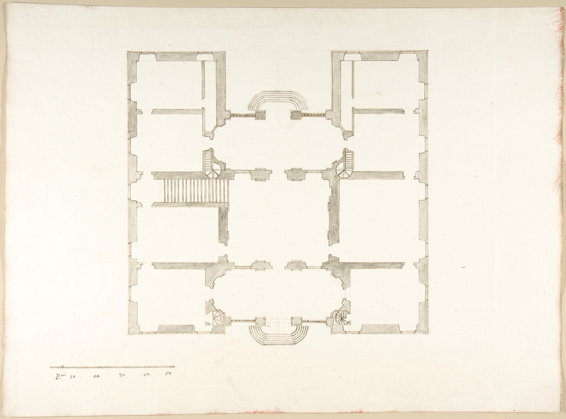
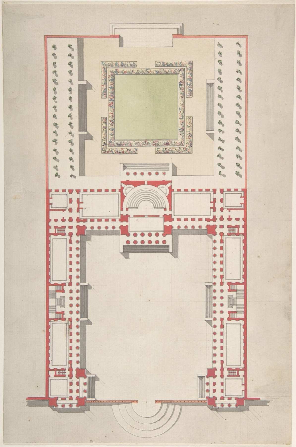
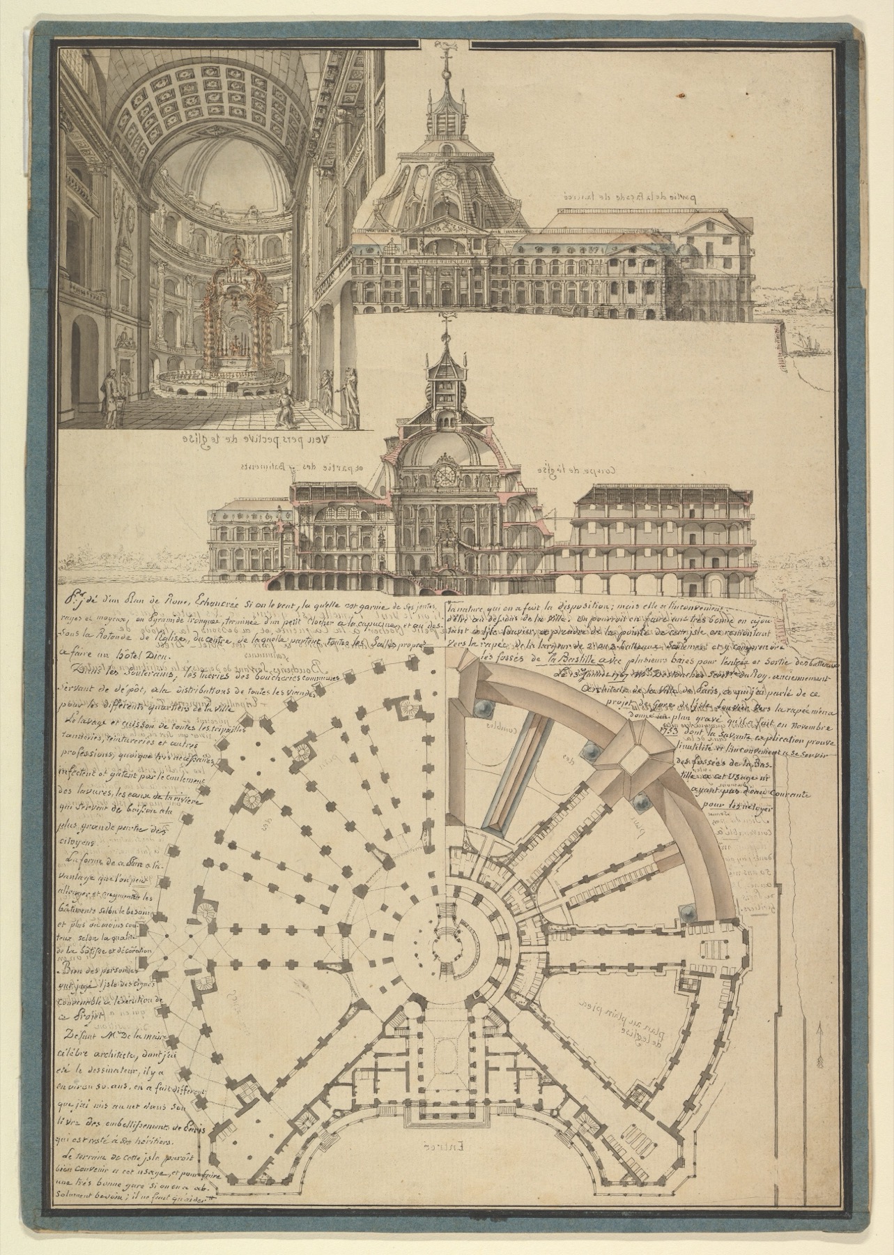
A plan is a conventional horizontal cut, not an aerial photograph. Wall weight, doors, stairs and openings rely on graphic conventions; annotations must tell the reader which floor, where the section cuts, which direction is north, and what scale or measured dimensions apply. A beautifully shaded plan may help explain spatial hierarchy, but wash colour alone does not certify material or the as-built thickness of a wall. The Met’s coloured historic plans make the range of uses visible: a formal project proposal and a measured survey may both use red, grey or green, but the legend and purpose of each individual sheet determine what those hues mean. [1], [8], [9], [22], [23], [32], [33], [34]

Text alternative for the diagram
The three projections are teaching descriptions of an imagined building, not measured views of a named object.
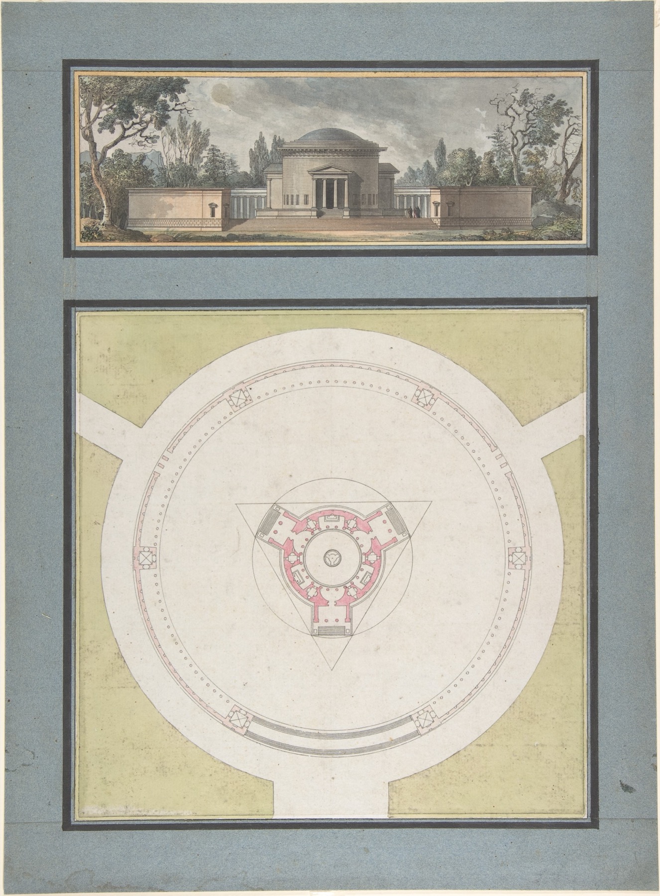
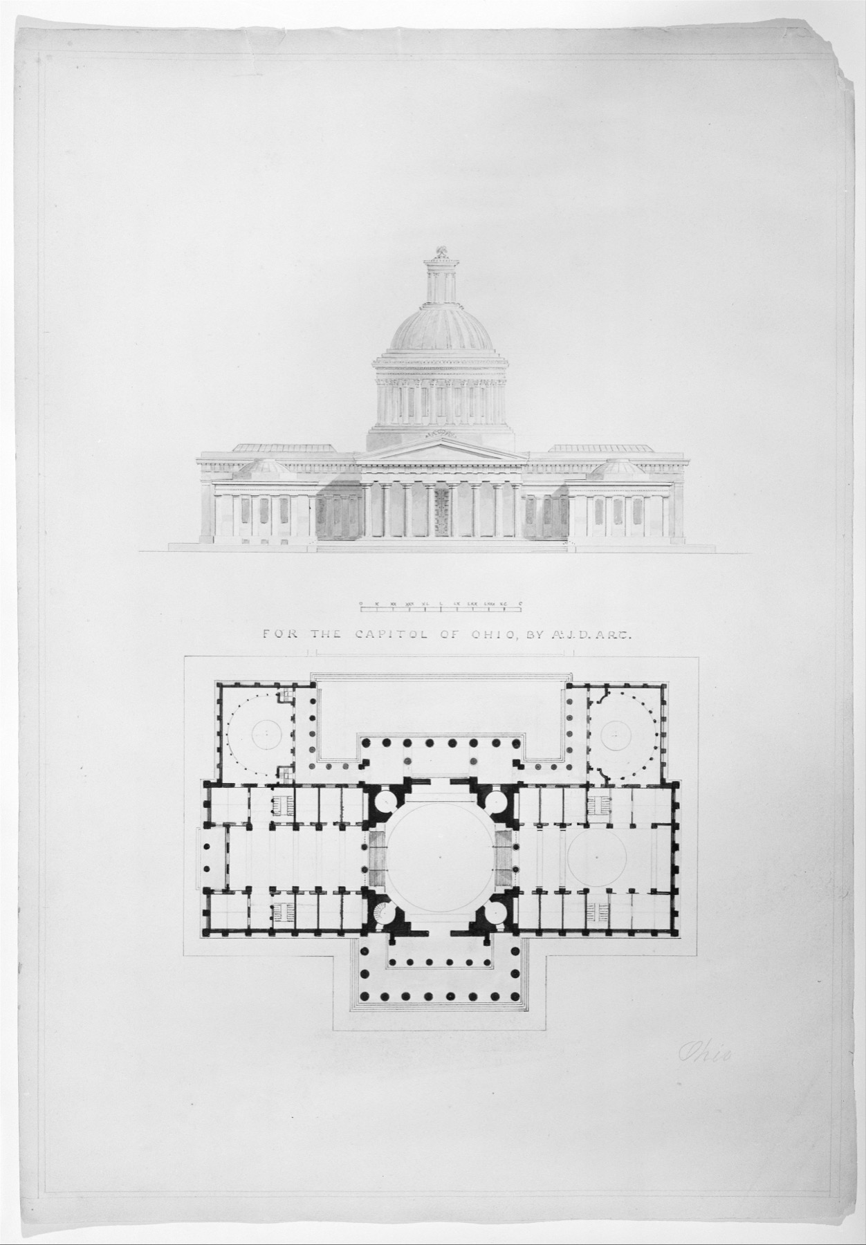
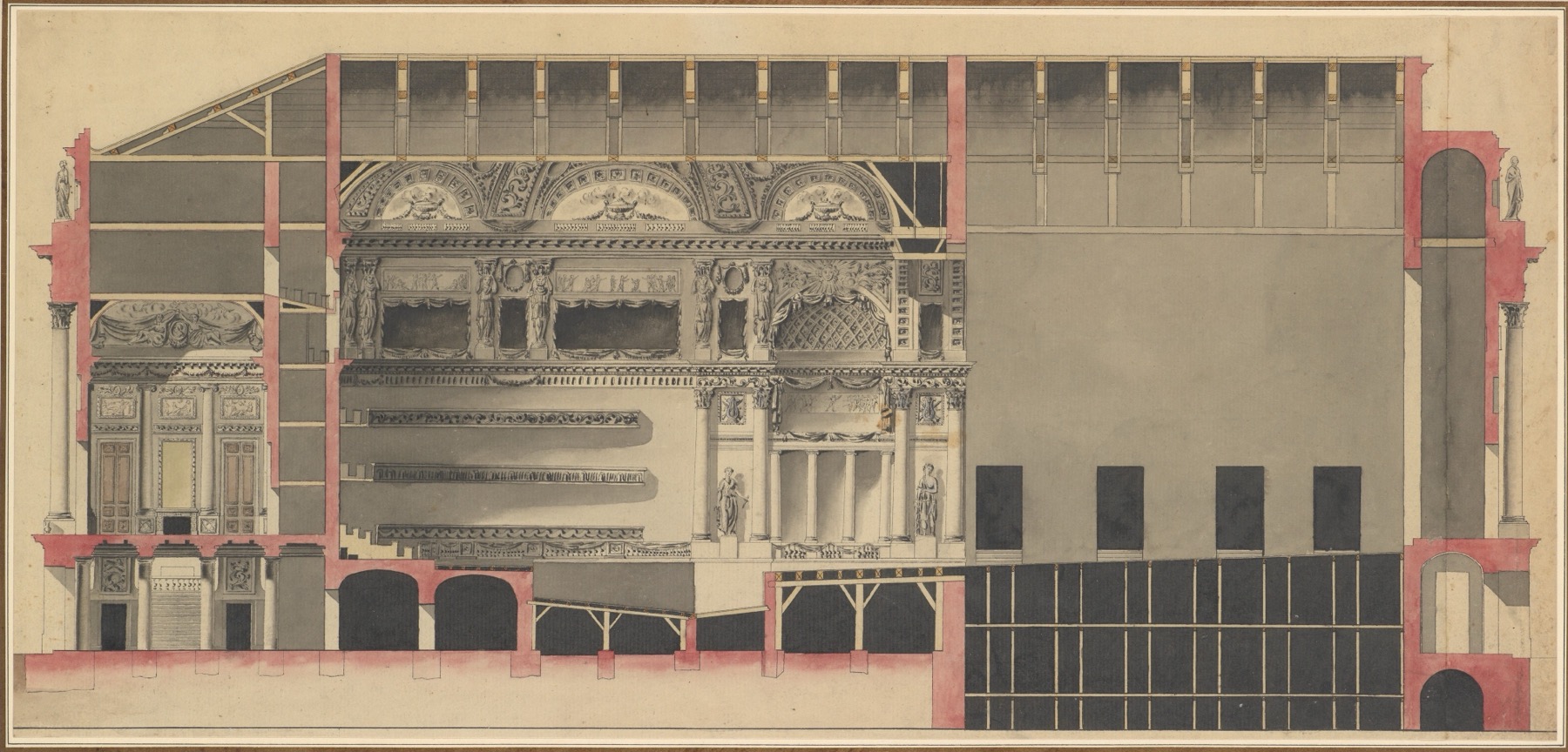
An elevation projects a face without perspective convergence. It can compare bays and roof line, but a face cannot show the full organization behind it. A section cuts vertically through levels and thickness; the plan must indicate where that cut was taken, while the section needs a matching reference. A single sheet can bring several views together, as Jean Nicolas Sobre’s late eighteenth-century temple project or Alexander Jackson Davis’s nineteenth-century designs do. Combined views are efficient only when their labels, scales and statuses remain decipherable. A section of a theater can reveal roof framing, balcony, stage and voids that an outside elevation hides; its drawn interior decoration may also make a persuasive promise rather than document an executed finish. [22], [23], [34], [35], [36], [37], [38]
The National Park Service’s HABS rules make the graphic grammar particularly explicit for measured historic buildings. They govern line weight, notes, room names, stair-direction arrows, title blocks and the name of the delineator. Thick and thin lines can mark significance, but a generic hatch can invent a material pattern that was not observed. The guidelines are not the worldwide rule for every new-building design. They illustrate why a key and accurate observation matter when an apparently precise line will be read as evidence. [23]
A set of drawings is a conversation among trades
Working sheets depend on each other. A plan locates a door; an enlarged detail explains the jamb and threshold; a schedule identifies a component; written specifications describe material and performance. A structural or services drawing must refer to the same dimensions and openings as the architectural sheet. The AIA’s working-drawing checklist asks for correct cross-references, explained symbols, coordinated disciplines and specifications, dimensions and independent checking. It also urges prompt circulation of revisions to people affected by a changed segment. The checklist is member-contributed and non-exhaustive, not a proof that one national drawing convention governs all practice. [22]

Text alternative for the diagram
One opening change can affect location, geometry, material and performance; this is illustrative communication, not a contract standard.
This multiplicity is visible in older craft documents too. Uffizi’s wooden-ceiling projections could communicate geometry to artisans; RIBA’s collections include specialist sheets by engineers, subcontractors and landscape architects. A drawing becomes consequential when another person has enough information to act, question, test or revise it. The familiar image of a solitary architect’s signature can obscure draughtsmen, surveyors, carpenters, masons and later archivists whose work determines both the building and what we can know about it. [1], [16], [20], [21], [22], [23]
The Nakai-family palace archive at Kyoto University gives another materially different way a sheet could communicate space. Its Edo okoshi-ezu are drawn, cut and raised so portions of paper can suggest walls in three dimensions. They belong beside plans, sections, elevations and repair records for palace work, rather than beneath a generic label of “Western model.” The archive has 1,067 palace records, but that count is a collection total, not evidence that a fold-up was used on every project or that each object carried a builder’s final instructions. [18], [19]
The Canadian Centre for Architecture’s House VI inventory separates Peter Eisenman’s geometric concept drawings, colour studies, a 1973 check/working set, subsequent alterations and later renovation or bid sets. It even retains site-survey and construction-photo copies. One neat sheet encountered alone might seem to contradict another, when the two record different decisions, audiences or phases. Their labels and dates are not clutter; they are part of the architecture. The CCA’s stated preference for exploratory and design-development material also shows how collecting priorities determine which kind of working conversation future visitors can hear. [4], [5]
Drawings made after the building
Measured drawings can be invaluable when they describe a building as found, especially if it has changed or no longer exists. They do not travel backward to become the initial architect’s plan. Tokyo University’s historic-building collection includes sheets made by students and commissioned draughtsmen during the Meiji to early Shōwa period. Some record structures later destroyed in war or before repair or relocation; the present object and the old survey are different witnesses. The maker and date of the survey need to stay visible if it is used to discuss earlier fabric. [20]
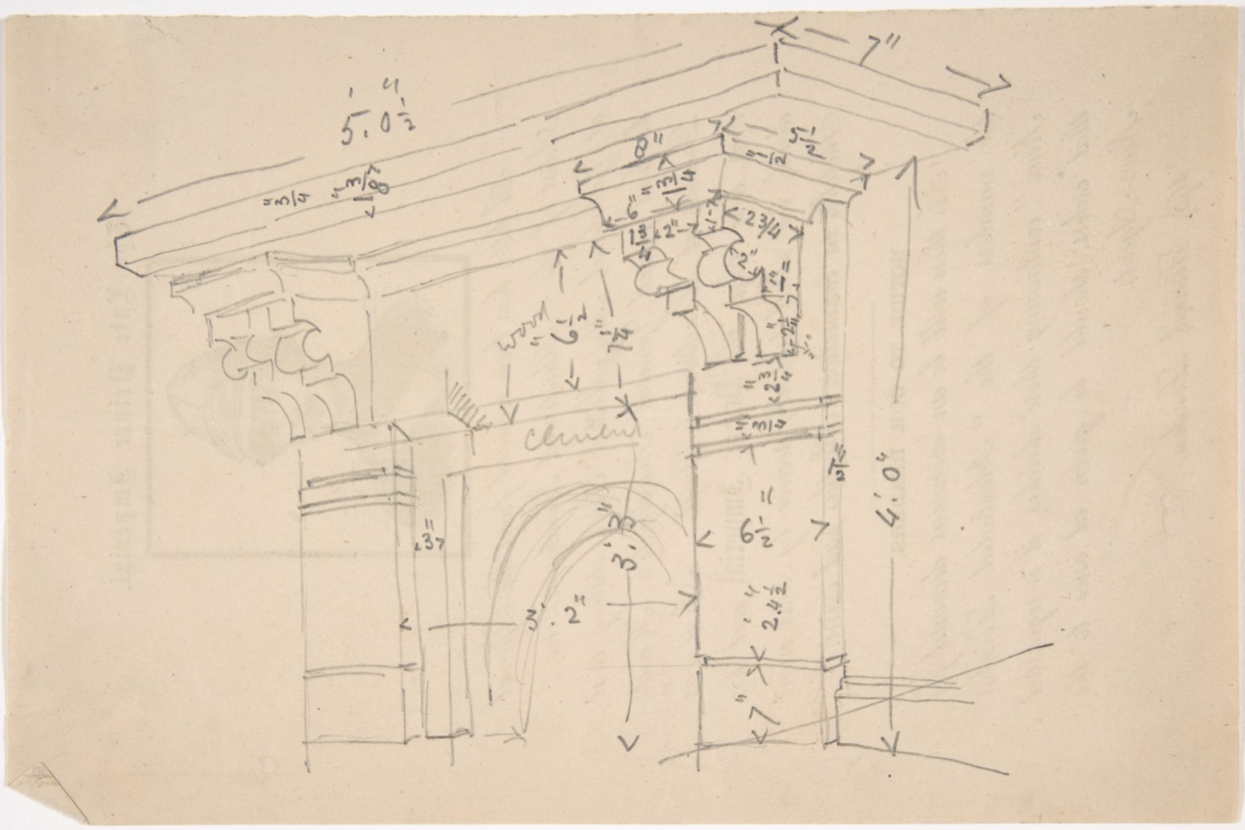
American HABS/HAER/HALS records similarly pair measured sheets with field notes, large-format photographs and written histories. The Library of Congress points out, in its discussion of Louis Kahn buildings, that a HABS measured plan is not Kahn’s original proposal or even an initial as-built sheet: decades of alterations can intervene. National Park Service documentation asks for sources when a sheet interprets a lost prior phase. A survey that shows a demolished wall hypothetically should separate that inference from the surviving masonry measured on site. More information can be present in a drawing without treating all its lines as observations of the same moment. [23], [24], [25], [26]

Text alternative for the diagram
An inferred earlier phase needs documentary or physical sources; it should not share the apparent evidentiary status of observed masonry.
Historic survey practices are themselves diverse. Dosio’s Roman-temple study and Kyoto’s palace repair records cannot simply be re-labelled as HABS drawings. The University of Tokyo archive was produced in part through education and hired documentation; Mexico’s UNAM architecture fonds preserve school records, plans, posters and photographs alongside professional archives. The Mexican Acervo de Arquitectura Mexicana now encompasses engineering and urbanism as well as named architectural practices. Clara Porset’s design archive includes plans, notes, letters and photographs, reminding readers that spatial and object-making histories do not belong only to a list of male “master architects.” These holdings are institution-specific evidence, not counts of every Japanese or Mexican drawing ever produced. [15], [18], [20], [21], [23]
Original, copy, blueprint and scan
“Blueprint” is often used loosely for any architectural sheet. It should name a particular reproduction process, not stand for plan, design or authority. RIBA’s policy lists traced, photographic, ferro-prussic, diazo and other nineteenth- and twentieth-century copies; it notes that multiplying an image sometimes left no singular original sheet. A copy can preserve a design that no longer survives otherwise, but its maker, method, annotations and date may differ from those of the initiating drawing. The faded mark on a tracing, the inscription added to a print and the image on a scan are not interchangeable originals. [1]

Text alternative for the diagram
The chart lists documentary statuses, not a compulsory chronological path for every project.
Archives themselves make another set of versions. RIBA’s scanned catalogues give dates, media, inscriptions and provenance for many holdings but warn that OCR and removed blank pages can disrupt searching and pagination. The Library of Congress describes about 40,000 architectural, design and engineering drawings through approximately 3,900 catalogue records: several sheets can share one record, and fragile originals are served by advance appointment. Those counts describe the collection and its cataloguing structure, not the number of buildings represented. The CCA can group conceptual and working material, photocopies and a later survey inside one project description. The search-result thumbnail is a useful door into an archive, not enough to decide authorship or original status alone. [3], [4], [5], [25]
Paper and media affect what can be inspected. Library of Congress digitization guidance warns that fragile tracing paper, loose chalk and iron-gall ink may be harmed by inappropriate handling or pressure; glass must not simply be laid on an artwork to make it flat for scanning. Getty’s paper conservation staff study, house and rotate works on paper. Kyoto University repaired deteriorated Nakai materials before digitizing its palace group and made high-resolution joined images of large drawings without contact scanning. The online picture greatly expands access, but a stitched view cannot always convey a sheet’s fold, verso or the physical raising of an okoshi-ezu. This last distinction is an inference about what a flat screen can show, not a claim that the digital archive is deficient. [18], [27], [28]
A drawing as a historical witness
Before relying on an attractive sheet, identify the project and record, its maker, title, medium, scale, date, archive number and any revision or reproduction statement. Determine whether it describes a proposed arrangement, an executed phase, a later observed condition or an interpretation. Compare it with another view or kind of evidence when a consequential claim is at stake: a plan with section, a working detail with specification, a proposal with survey, or a survey with photograph and field notes. The mismatch may indicate change rather than error. [1], [3], [4], [5], [10], [22], [23], [24], [25], [26], [27], [28]
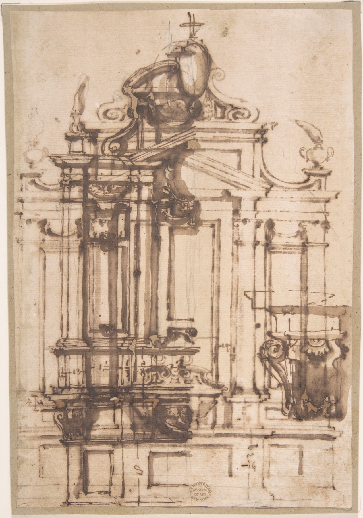
The drawings reproduced here have distinct purposes: particular proposals, studies, copies and observations, not interchangeable architectural decoration. One French medieval sheet has no known built counterpart; a Villa Giulia section is a three-joined-sheet artifact whose catalogue does not alone prove original-design status; a nineteenth-century American drawing may show front and section on one side and other views on the reverse. A drawing can be both visually compelling and limited in what it proves. Attending to those limits makes the graphic imagination, the labour of drafting and the history of construction more—not less—interesting. [7], [31], [32], [33], [34], [35], [36], [37], [38], [39]
Explore RELATED Artworks and Records
These sheets carry distinct documentary and design roles.
Sobre’s temple project
A proposed temple joins plan and elevation.
Met Open Access object imageFrench Gothic vellum sheet
A likeness does not establish an executed design.
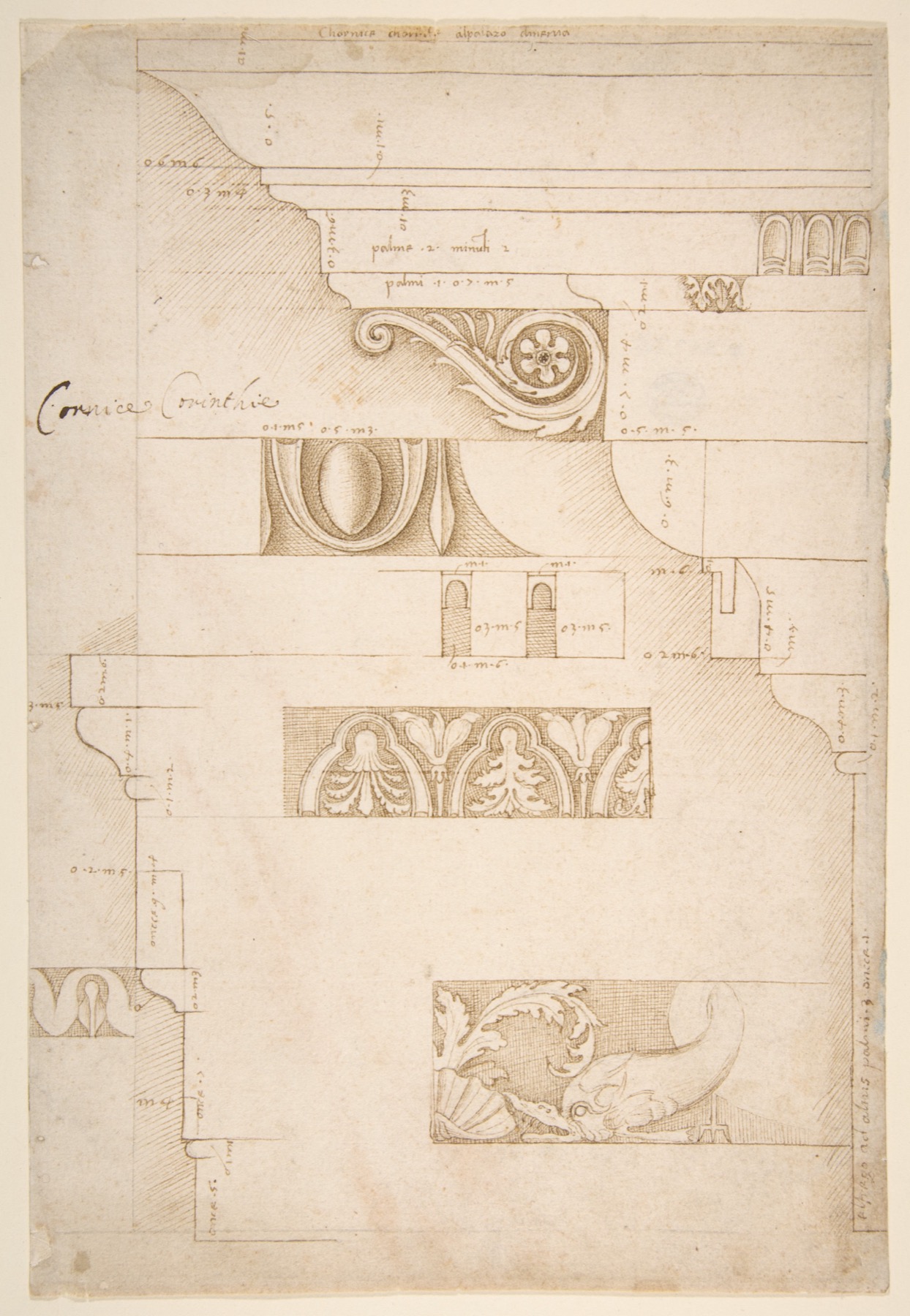
Met Open Access object imageSangallo measured profiles
Measured ancient fabric informs later study.
Met Open Access object imageChapel-and-hospital counterproof
The reproduction process is visible in the image.
Met Open Access object imageWatch: Architectural Drawings
Three institutional films; illustrated previews are not film frames.
Learning from Roriczer’s Pinnacle
Modern animation of a 1486 plan-to-elevation method. [29]
Preview: original editorial illustration, not a film still.
Reconstructing a Gothic Vault Design
A one-minute demonstration based on a fifteenth-century Vienna drawing. [40]
Preview: original editorial illustration, not a film still.
Plan as Perimeter
Recorded conversation on drawing and historical references, English with French subtitles. [41]
Preview: original editorial illustration, not a film still.Explore Kyoto University’s Nakai drawing archive: a visual record collection, not a video. [18]
Frequently Asked Questions
No. Designs, studies and competitions can remain unbuilt, and the Met does not identify a built counterpart for its French Gothic sheet. [1] [7]
They may be setting-out or exploration. York’s Campbell study shows both alternatives and engraver preparation. [10]
The plan locates the section cut, while the section shows heights, thickness and levels along that declared line. [22] [23]
Not necessarily. It is a reproduction process with its own date, maker and possible annotations. [1]
References
- Royal Institute of British Architects, Collections Development Policy (2024), especially pp.10–11, 23–25.
- Royal Institute of British Architects, Palladio drawings research programme.
- Royal Institute of British Architects, catalogues to the Drawings Collection and OCR/access notes.
- Canadian Centre for Architecture, Prints and Drawings collection history.
- Canadian Centre for Architecture, House VI project archive record.
- Metropolitan Museum of Art, Gothic by Design: Inside the Galleries.
- Metropolitan Museum of Art, French Architectural Drawing, 1450–1500 (68.49).
- Metropolitan Museum of Art, Renaissance Drawings: Material and Function.
- Mauro Mussolin and Femke Speelberg, Metropolitan Museum of Art, How to Read (and Display) Architectural Drawings.
- Joanne E. O’Hara, Colen Campbell and the Preparatory Drawings for Vitruvius Britannicus, University of York doctoral thesis (2010), full PDF directly read pp.39–55, 114–148.
- Jurjen S. Zeinstra, Thinking Perspectives: The Layered Meaning of Heinrich Tessenow’s Drawings (1901–1926), TU Delft doctoral thesis (2022), full PDF directly read pp.9–20, 35–47, 159–169.
- Bibliothèque nationale de France, Les collections de dessins.
- Bibliothèque nationale de France, Dessins d’architecture dans les collections de la BnF.
- Bibliothèque nationale de France, Robert de Cotte architecture/décor catalogue description (795-page inventory not directly read).
- Gallerie degli Uffizi, Giovanni Antonio Dosio, Tempio di Antonino e Faustina.
- Gallerie degli Uffizi, I Cieli in una stanza architectural ceiling-drawing exhibition.
- Politecnico di Milano, Piero Bottoni archive: academic study drawings, 1921–26.
- Kyoto University Library, Nakai-family palace subcollection (Kinri no bu) (Japanese).
- Kyoto University Library, Nakai-family family collection overview (Japanese).
- University of Tokyo, historic-building measured-drawing collection (Japanese; image reuse by permission).
- Universidad Nacional Autónoma de México, Facultad de Arquitectura historical fonds and Acervo de Arquitectura Mexicana (Spanish).
- American Institute of Architects, Quality Control: Preparation of Working Drawings (2023, non-exhaustive member practice).
- US National Park Service, HABS Guidelines: Measured Drawings, full PDF directly read, especially §§5.7–5.9.
- US National Park Service, Secretary of the Interior’s documentation definitions/standards.
- Library of Congress, Architecture, Design and Engineering Drawings collection and HABS/HAER/HALS collection.
- Library of Congress, Exploring Buildings by Louis I. Kahn in the Historic American Buildings Survey.
- Library of Congress Preservation, digitizing fragile graphic materials.
- Getty Museum, Paper Conservation department.
- Metropolitan Museum of Art, Learning from Roriczer’s Pinnacle video (2026).
- Metropolitan Museum of Art, object 342267, anonymous Italian architectural drawing.
- Metropolitan Museum of Art, object 360501, Villa Giulia, section.
- Metropolitan Museum of Art, object 335428, architectural ground plan by Paul Guillaume Lemoine.
- Metropolitan Museum of Art, object 344231, plan by Pietro Paolo Coccetti.
- Metropolitan Museum of Art, object 395937, Ohio Capitol design by Alexander Jackson Davis.
- Metropolitan Museum of Art, object 383987, Jean Nicolas Sobre Trinity temple project.
- Metropolitan Museum of Art, object 362067, theatre section by Nicolas Marie Potain.
- Metropolitan Museum of Art, object 394162, Davis Belmead recto/verso drawings.
- Metropolitan Museum of Art, object 27292, Lefuel’s Nieuwerkerke interior drawing.
- Metropolitan Museum of Art, object 471868, French Gothic vellum architectural drawing.
- Metropolitan Museum of Art, Reconstructing a Gothic Vault Design video (2026).
- Canadian Centre for Architecture, Plan as Perimeter streaming film (2017).
Explore RELATED Architecture
These built-place pages show why plans, perspective, photographs and later records must be read together.
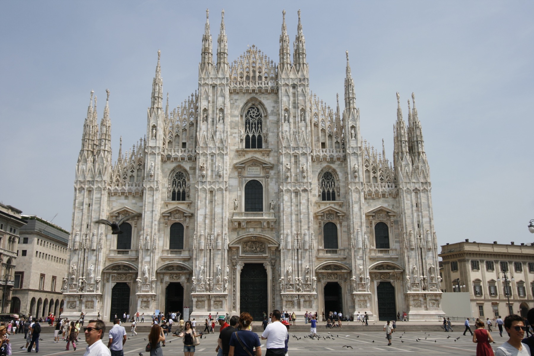
Milan Cathedral
Design and geometry changed through argument and building.
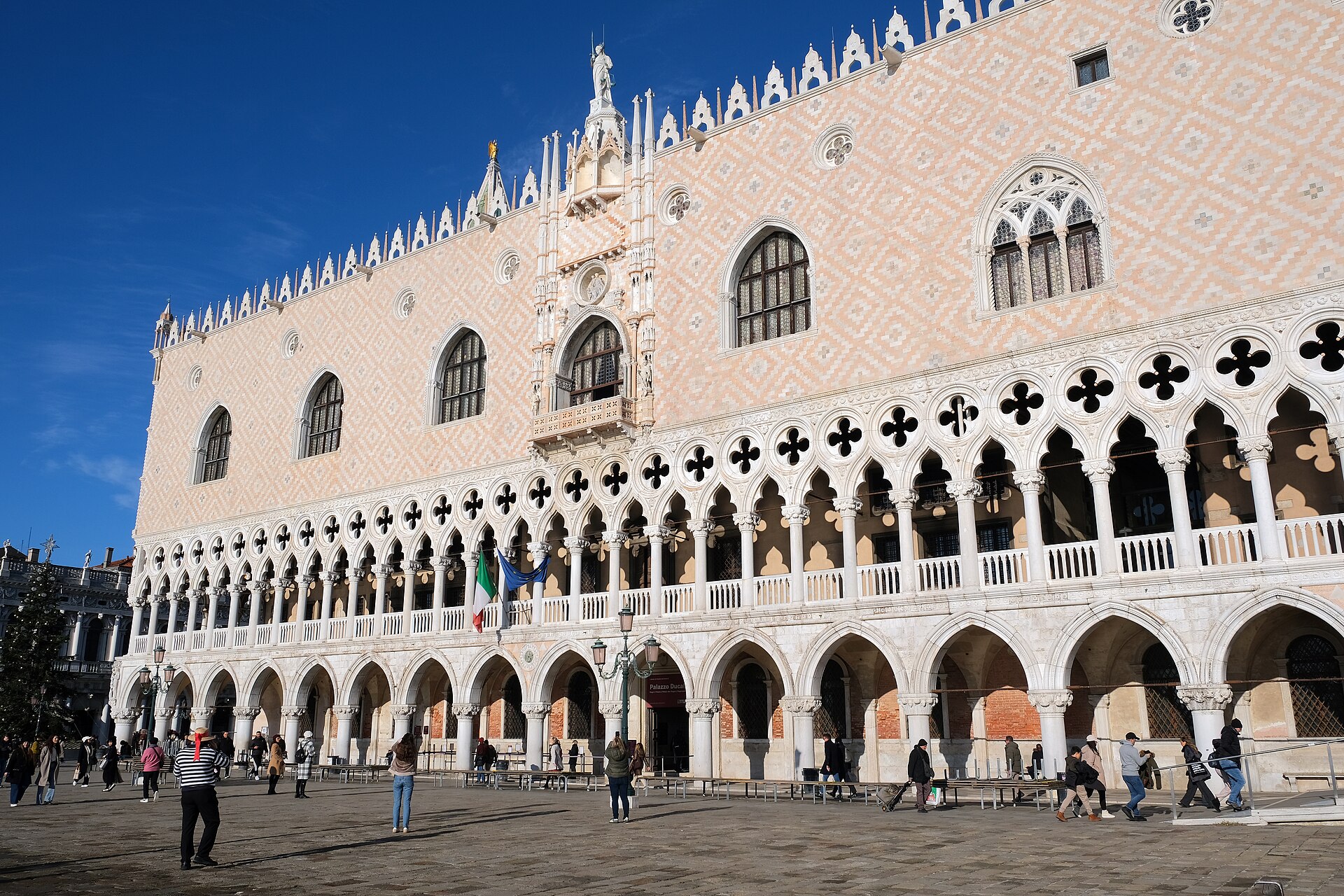
Doge's Palace
A facade conceals a long sequence of alterations and uses.
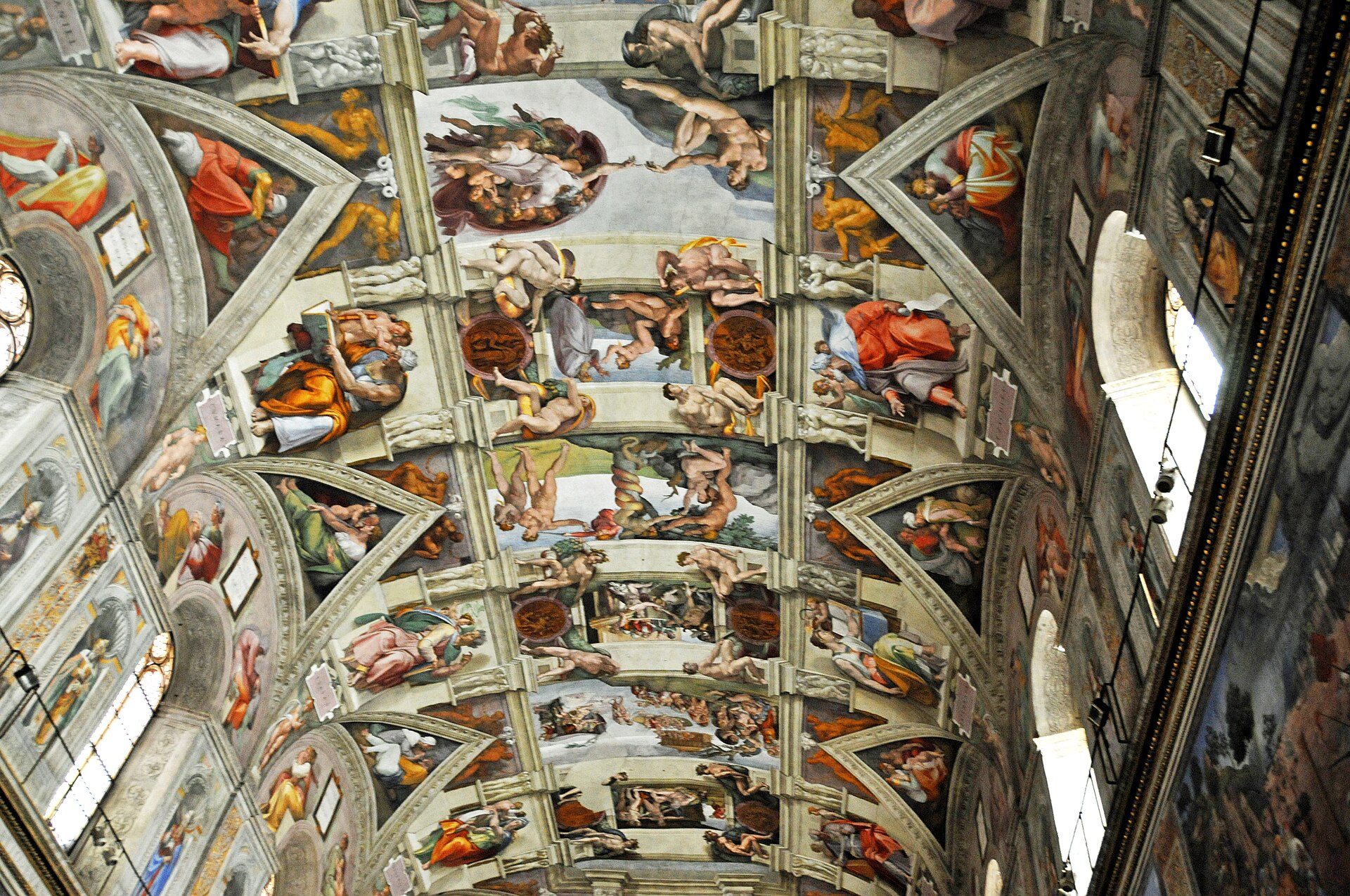
Sistine Chapel
Architectural fabric and painted programmes have different records.

Borobudur
Plan and visitor sequence reveal different spatial relations.

Machu Picchu
Ruins and later surveys mediate the reading of built terraces.
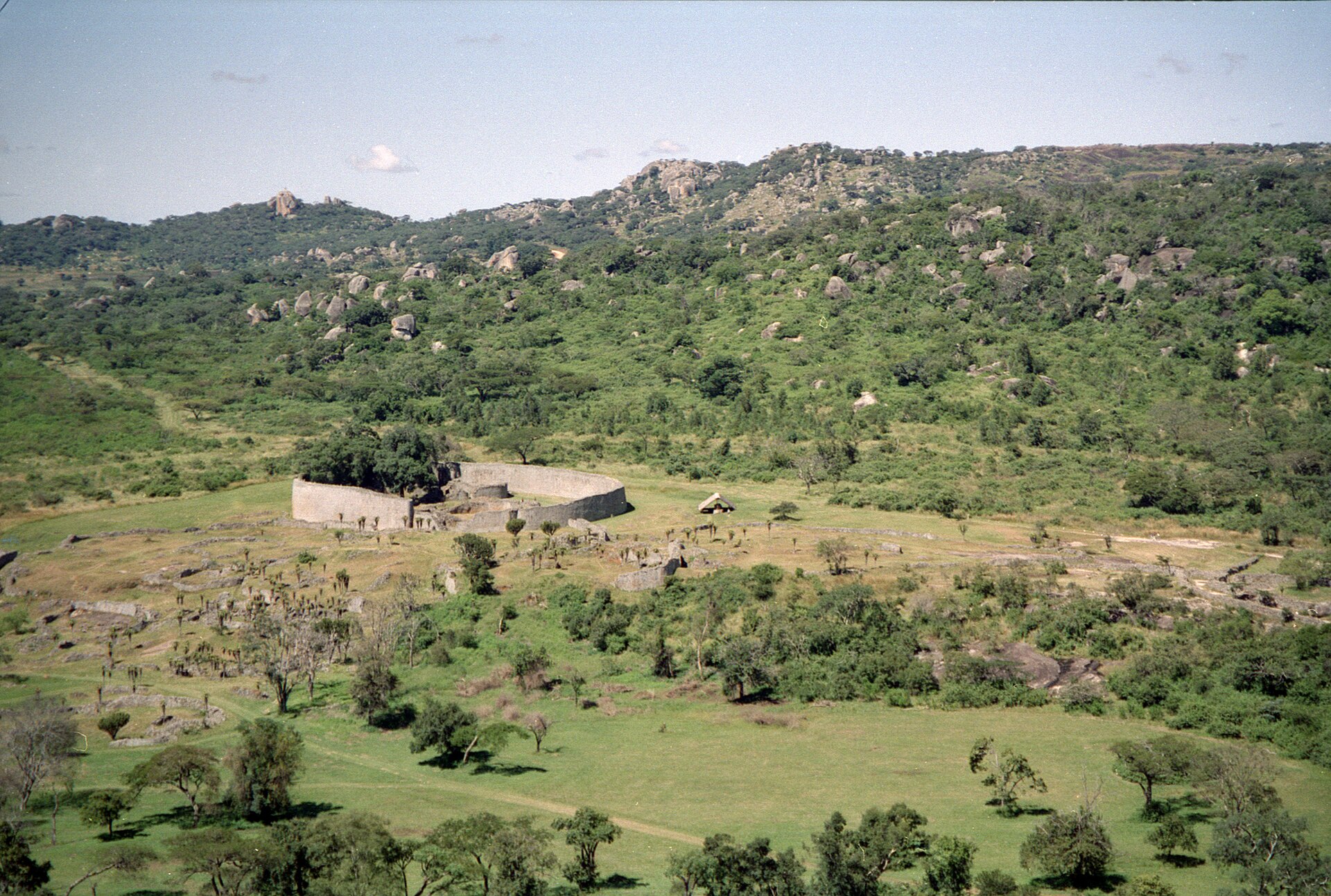
Great Zimbabwe
Heritage records must distinguish fabric from later inference.
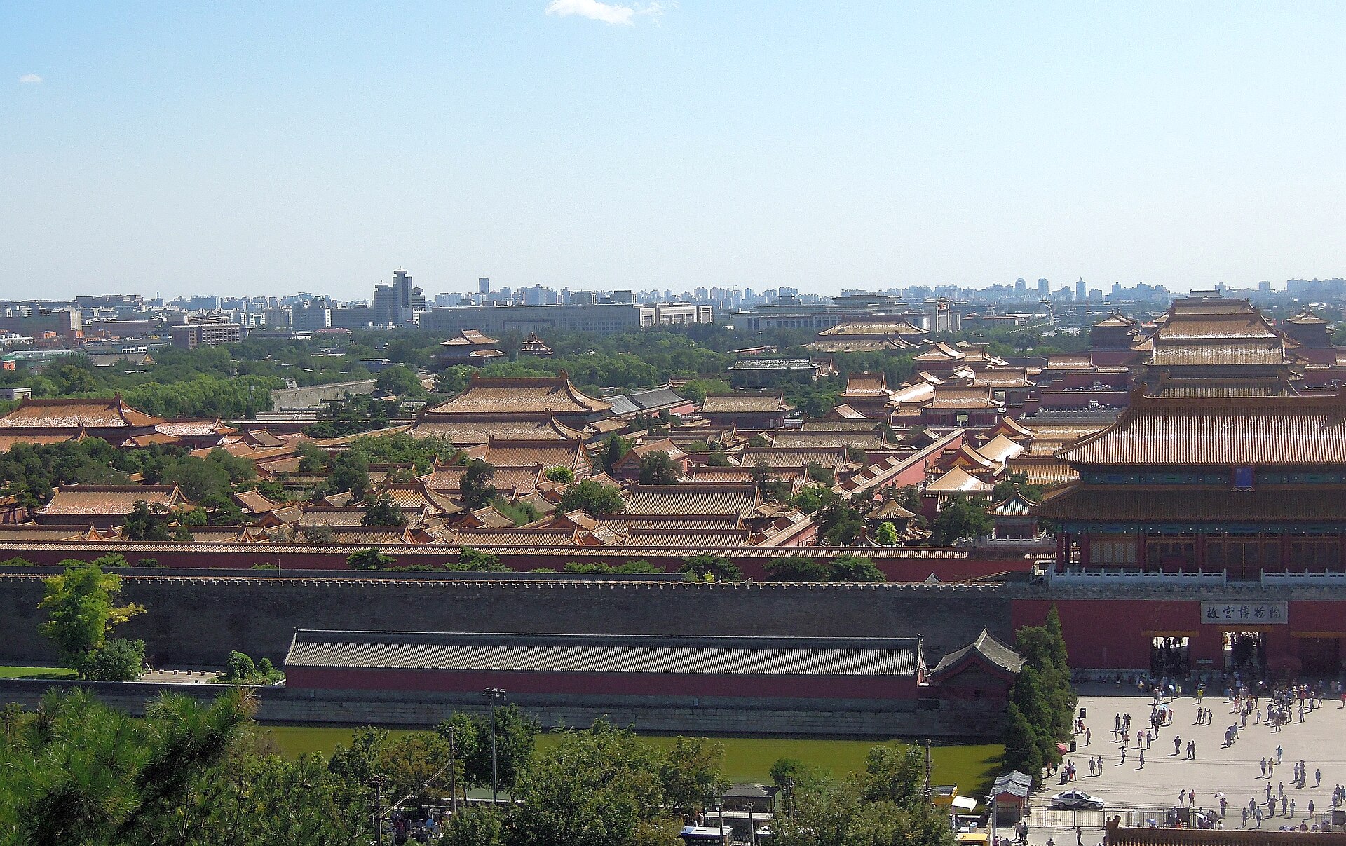
Forbidden City
Palace plans and surviving courts changed across reigns.

Teotihuacan
Archaeological plan and exposed monuments are not the whole city.