


 by Tom Gurney
Tom Gurney BSc (Hons) is an art history expert with over 20 years experience
Email: tomgurney1@gmail.com / Phone: +44 7429 011000
Drawing, Model, Building and Record
A building can be imagined in a few searching lines, explained to a client through a model, coordinated on measured sheets, described in specifications, and recorded again after construction. These are all forms of architectural representation, but they do not say the same thing. A perspective can convey an approach or atmosphere while concealing dimensions; a plan can disclose rooms and routes while suppressing height; an archival survey may show a building decades after the architect's work. Reading an image therefore begins with a question less glamorous than “What does it look like?”: who made this record, when, for whom, and to do what? [1], [2], [3], [4], [5]
The range is visible in architectural archives. The Royal Institute of British Architects describes a collection approaching a million drawings, with models and office instruments as well. The Canadian Centre for Architecture preserves conceptual, presentation and working drawings, models, photographs and digital carriers from the same practices. France's national library holds architectural drawings made for learning as well as design and display; a Mexican university archive preserves originals and copies of plans, sketches, perspectives and models. A single project can leave many kinds of record, each a selective witness to a different decision. Architecture's “design language” is not a closed dictionary of symbols. It is a changing set of graphic and physical conventions through which people explore an idea, assess it, communicate it and sometimes contest it. [1], [2], [3], [4], [6], [7]
At a Glance
- MediaSketches, orthographic and experiential drawings, models, specifications, digital files and later surveys each answer different questions. [1], [2], [3], [4], [5]
- StatusProposed, working, as-surveyed or reconstructed? Maker, date, audience and provenance govern what a record establishes. [5], [8], [9], [10]
- Orthographic viewsPlan cuts horizontally; elevation projects a face; section cuts vertically. Each omits as well as shows. [8], [11]
- Experiential viewsPerspective and perspectival sections suggest depth and sequence, not dependable measured dimensions by themselves. [8], [12], [13]
- ModelsA study object and a data-rich BIM model serve different tasks; neither proves a building was constructed. [3], [14], [15], [16]
- Different traditionsItalian Renaissance mixed-view sheets and Edo Japanese okoshi-ezu fold-ups follow distinct histories. [12], [17], [18]
- ConstructionDrawing, detail, notes, revisions and specifications must coordinate among makers; a polished rendering cannot replace them. [19], [20]
- HeritageSurveys capture condition when documented; an inferred earlier phase requires its source to be identified. [8], [9], [10]
Contents
- Choosing what to show—and what to leave out
- Sheets, models and patrons before modern practice
- Different traditions of a drawing that becomes a model
- A project is represented more than once
- Plans: routes, cuts and use
- Elevation, section and the building's thickness
- Perspective, axonometric and the experience of a place
- Physical models can think, test and persuade
- Digital drawing, information models and fabrication
- Records after building: observation is not original intention
- Who understands a drawing?
- Images in public culture, not just at the building site
- How to read an architectural image responsibly
Explore Architectural Drawing and Representation
Read the individual guides to drawing conventions, models and ways of representing architecture.
Choosing what to show—and what to leave out
Representation is an act of selection. A maker chooses viewpoint, scale, cut line, line weight, colour, labels and degree of finish. The choices foreground some relations and silence others. A rapidly drawn courtyard diagram might make an entrance and a series of open spaces legible while leaving wall thickness unresolved. A contractor's sheet must do almost the reverse: explain what meets what, at what level and with which reference to the written requirements. The distinction is not between careless and careful drawing. Each record is careful about a different question. MIT's architectural-design teaching explicitly treats representational tools as participants in forming architectural meaning rather than neutral translations of ideas already complete in the designer's head. That is a teaching proposition, but archives make the practical point plain: the same project accumulates different kinds of explanation because different people must act on it. [2], [3], [19], [21]
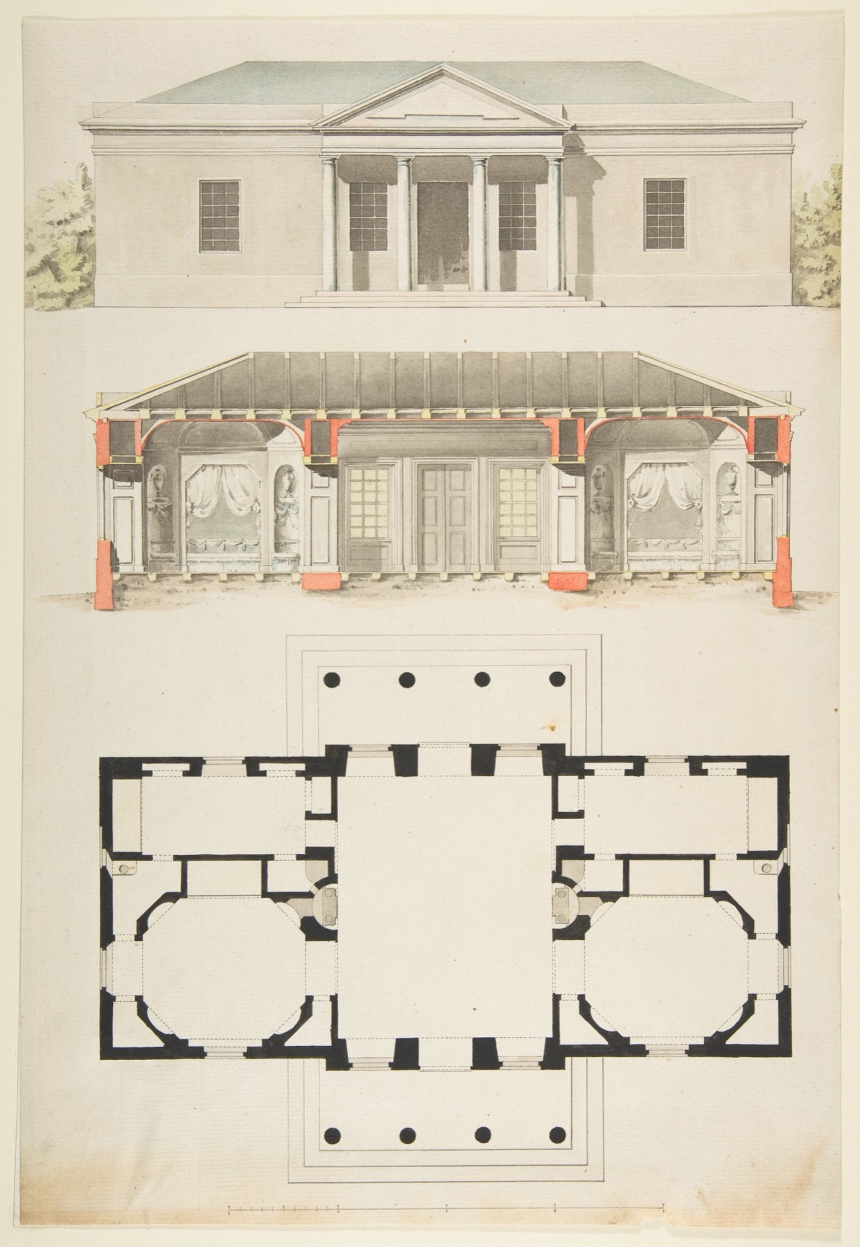
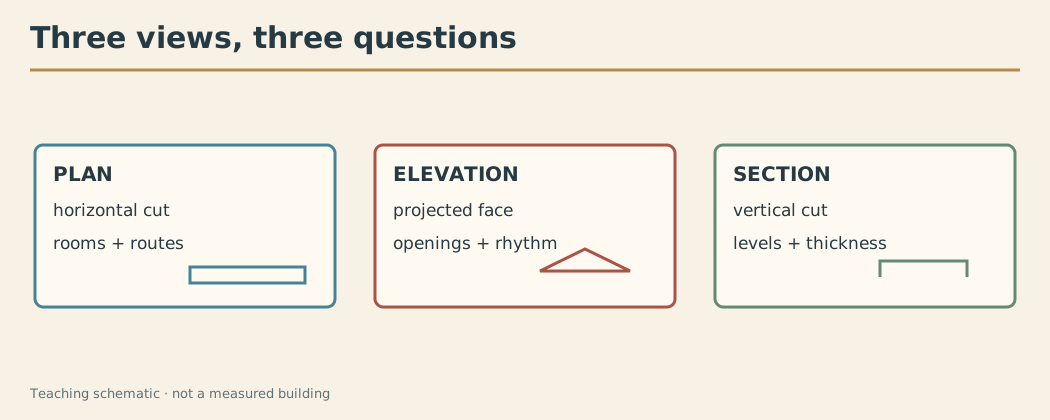
A projection is especially powerful because it establishes repeatable rules. In an orthographic plan, measurements need not diminish with apparent distance from the eye. Doors, stairs and wall junctions can be placed in stable relation, provided a key explains conventions such as cut height and door swings. An elevation isolates a face, but it cannot tell the reader what lies deep behind it. A section makes thickness, level changes, a roof and a stair more explicit; it can hide circulation at right angles to the cut. Three sheets, cross-referenced, answer more than one attractive perspective. A model can add relationships too, though it also abstracts: opaque walls hide interiors, a removable roof reveals them, and a sectional model changes the evidence once more. [8], [11], [12], [14]

Text alternative for the diagram
A plan is a horizontal cut showing rooms and routes. An elevation projects a face and its openings. A section cuts vertically through levels and thickness. All three depicted views are teaching schematics, not surveyed fabric.
The distinction matters to a non-specialist who finds two images of the same structure apparently contradictory. One may be a plan of an unbuilt proposal; another, a measured plan of its later altered form. The later plan is not a “corrected” designer's sheet unless the evidence says so. A drawing of a dome might be idealized, a decorative programme might be mounted inside a model, and an archive copy might preserve only part of a lost original. The caption is not a formality: it tells the reader what kind of architectural claim an image can support. [9], [10], [12], [22]
Sheets, models and patrons before modern practice
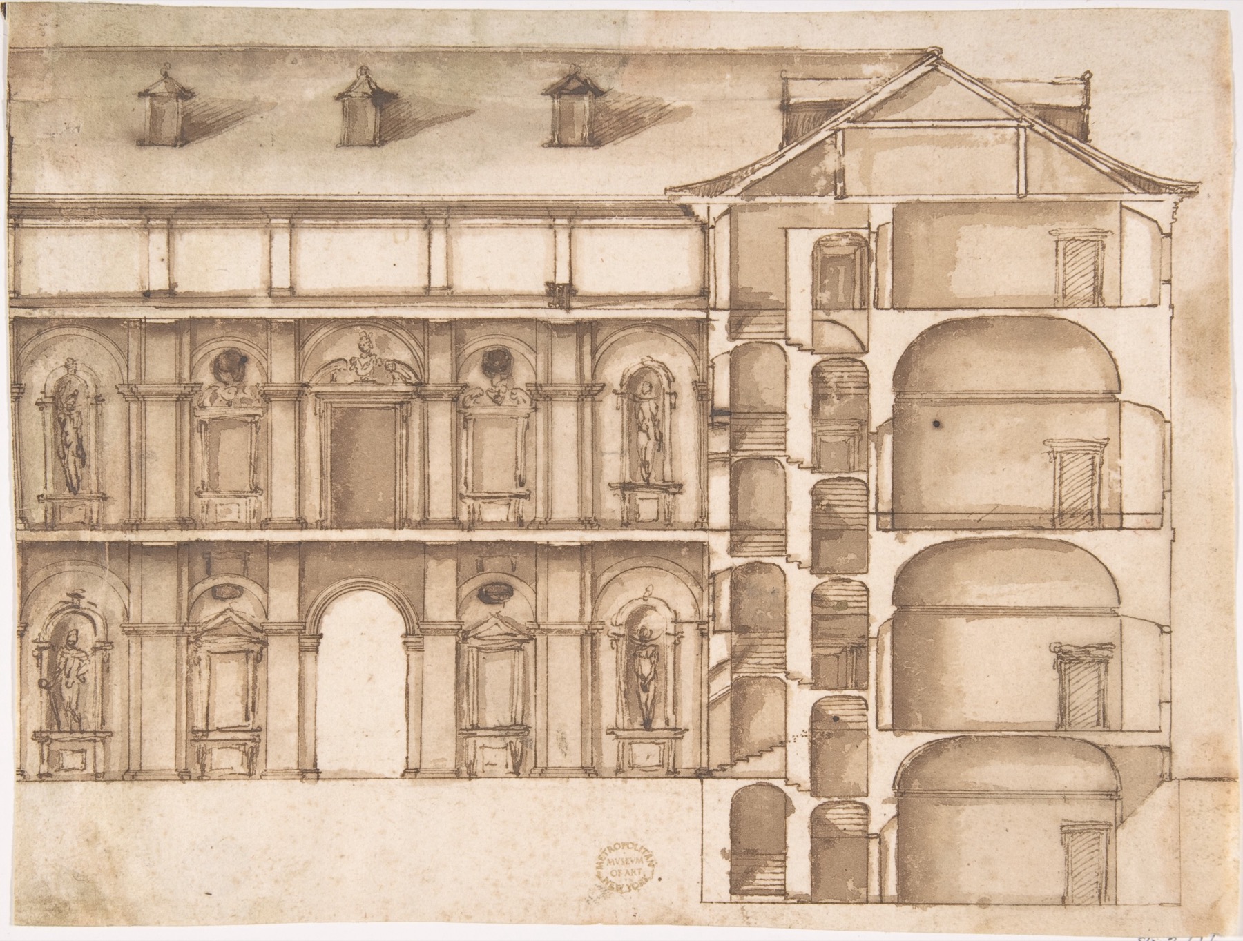
There is no defensible moment when architects first used a representation and then uniformly advanced to the next one. The Metropolitan Museum describes drawings and models serving patrons and builders in Renaissance Italy, sometimes on the same commission. One sixteenth-century altar drawing brought plan, elevation, side view and section together; foldable paper could make the sheet function partly as a model. Competition entries for a Florence cathedral facade could contrast an orthographic coloured drawing with a wooden model. These examples demonstrate practical flexibility, not a claim that all Italian builders had modern standardized drawing sets. A later plan of the Villa Giulia is a survey of existing fabric, not automatically Vignola's first design: the “old drawing” category includes records made after building as well as those made before it. [12]
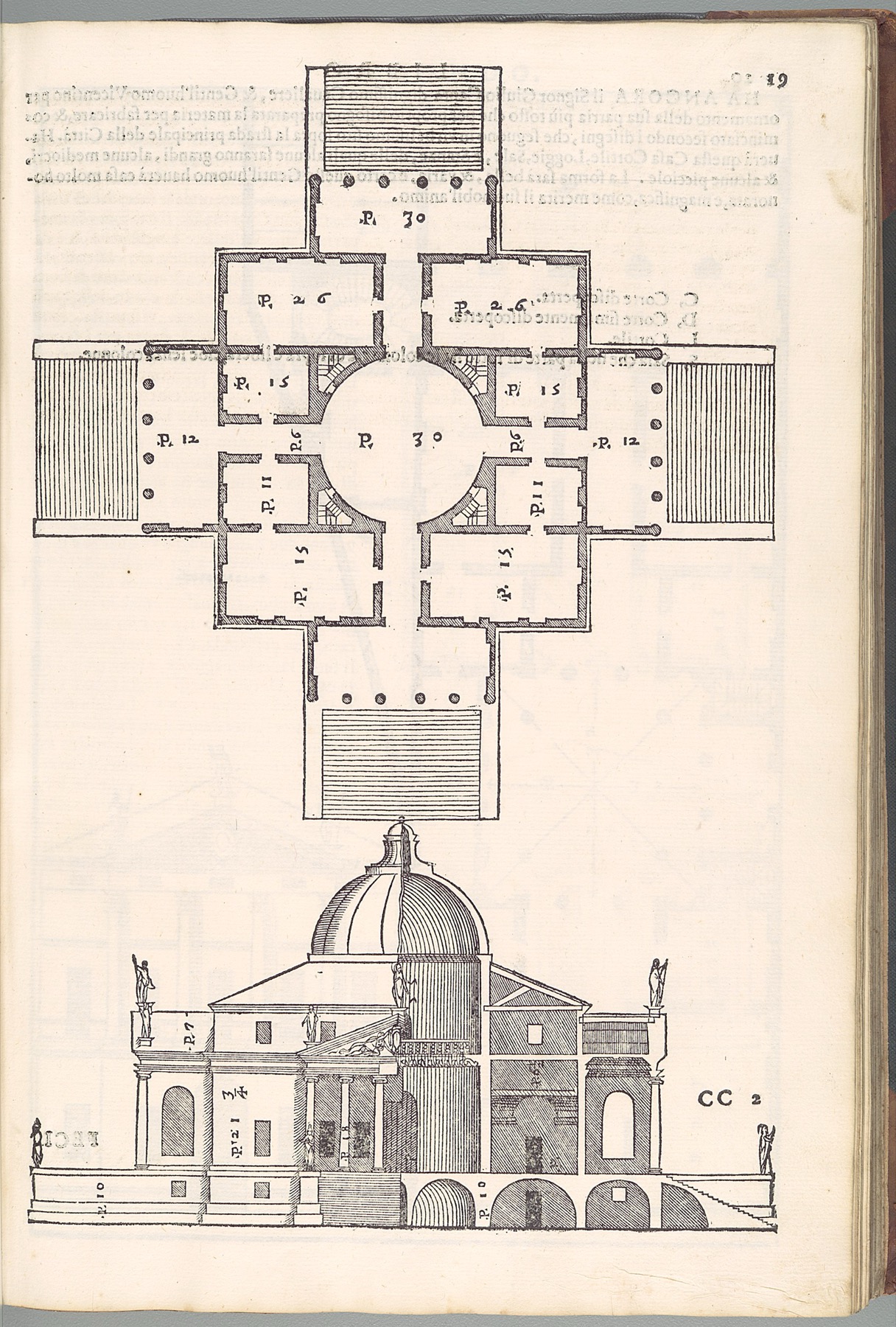
Print changed the possible audience. Palladio's I quattro libri dell'architettura, first published in 1570, circulated plans, elevations, sections, details and scales through woodcuts. A page could make a design or an exemplary building available to a reader who had never stood beside its maker. But a published figure is not a guarantee that a contractor built exactly its depicted form. Edition, plate, project status and the differences between the treatise's architectural argument and a commission's actual records should remain distinct. The Metropolitan Museum's sixteenth-century exemplar dates from 1581, later than the book's original issue; that small bibliographic difference itself is a useful reminder that an image's date may refer to a copy rather than a design event. [23]
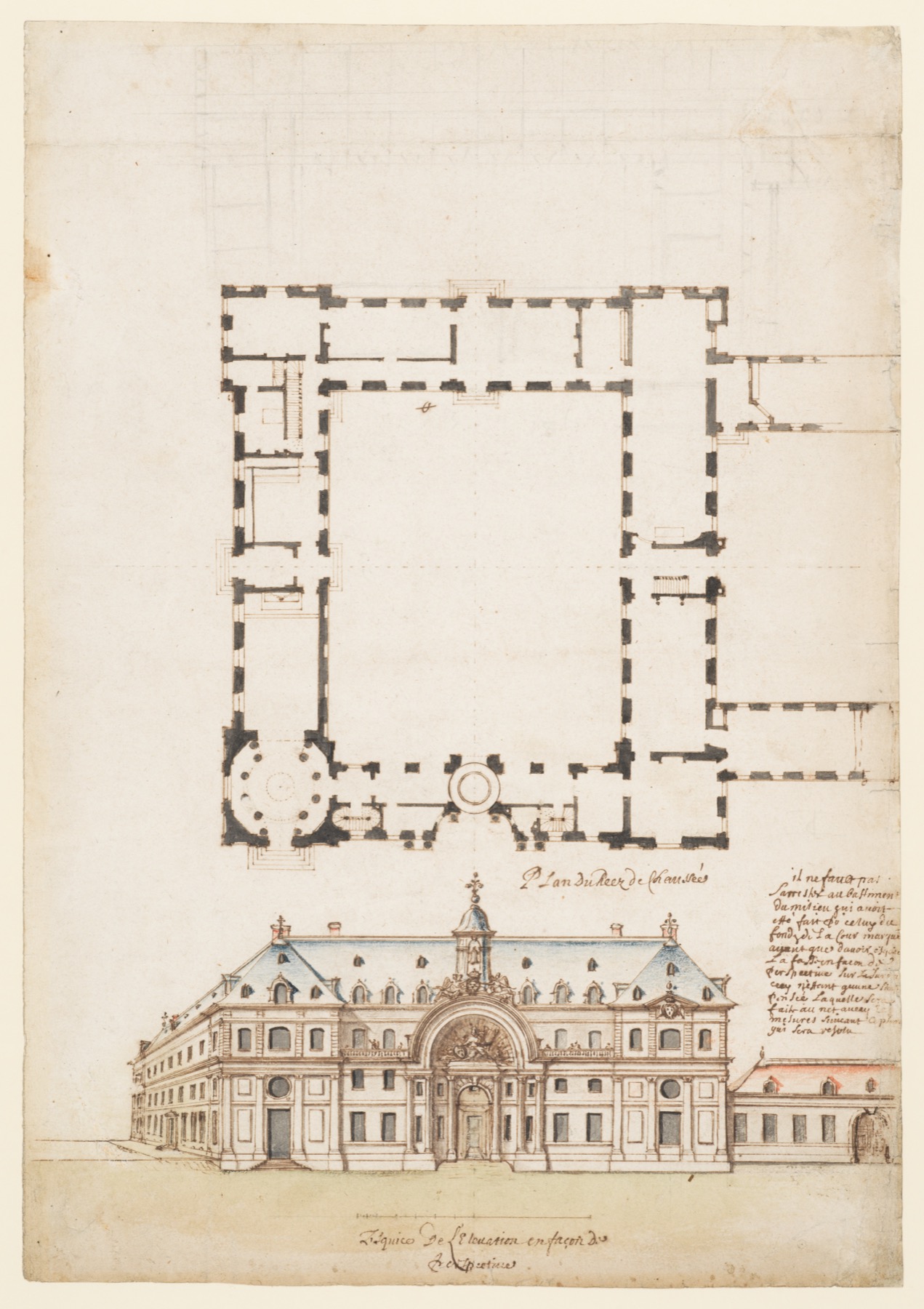
A French drawing from about 1650–70 in the same museum combines a perspective and floor plan, with faint chalk alternatives on the sheet. The visible changes caution against calling every polished view a final, fixed proposal. Historical studies of Pantheon drawings likewise distinguish measured fabric from an as-reconstructed ancient geometry. In some examples elements such as stairs are omitted in favour of an interpretative image. That omission may disclose a research question or an idealizing goal, not a licence to treat the drawing as a perfect measured record. [22], [24]
Different traditions of a drawing that becomes a model
The Kyoto University Library's Nakai-family archive preserves more than a thousand digitised Edo-period palace documents, including plans, sections, elevations, repair records and okoshi-ezu. The last term describes fold-up drawings whose cut and raised portions create a spatial object from a sheet. It is tempting to call this simply a Japanese version of a Western model, yet the archive shows a particular working tradition with its own material and institutional life. The documents may serve palace planning or repair; an archive note alone does not reveal the precise use of every surviving sheet. Still, they establish that a boundary between “flat drawing” and “model” was porous outside the familiar European examples. [17]
Kyoto's modern archival descriptions distinguish original drawings, blueprints and records of work, and its digitisation of Josiah Conder's designs points to later professional exchanges in Japan. Neither fact means the Edo sheet suddenly vanished in a global march toward imported standards. Older and newer conventions can coexist, and a repair drawing can be neither a founding design nor a mere reproduction. The original/copy distinction matters in Mexico as well: a 2022 UNAM report described about 180,000 documents across 31 collections, explicitly including original and copied plans alongside sketches, perspectives, models and office tools. The figures speak to that archive's scope on that date, not an exact census of Mexican architecture. [6], [7], [18], [25]

Text alternative for the diagram
This invented two-step schematic shows a plan marked for cutting and paper surfaces raised to make a three-dimensional spatial object. It is inspired by Edo okoshi-ezu but does not copy a particular Nakai artifact or fix its historical use.
A project is represented more than once
A designer may first use a diagram to compare possible routes or structural arrangements, then make a model to see how masses meet, then coordinate room and service positions, then issue details and specifications. These acts overlap. The RIBA Plan of Work 2020 gives a UK framework from strategic definition to use, with concept, spatial coordination, technical design, manufacturing and construction as distinct but sometimes overlapping stages. It does not prescribe one sheet per stage or describe every legal and professional system worldwide. Its value here is to make the difference between imagining an architectural form and enabling many people to make, hand over and occupy it visible. [20]
The record may also be remade for a client, planning authority, public exhibition, structural engineer, specialist fabricator or future conservator. A presentation image might refine an expectation of atmosphere without specifying every joint. A section might identify a roof or slab relation but still need a detail and written performance requirement. The American Institute of Architects' guidance on quality control for working drawings emphasizes coordinated notes, symbols, revisions, cross-references and specifications. If a revised wall line is not reflected in the door schedule or a material note, the drawing set can be internally persuasive and practically confusing at once. Designers and constructors work from negotiated, coordinated information, not from a solitary beautiful picture. [19]

Text alternative for the diagram
If an opening position changes on the plan, its junction detail and material or performance specification may also need revision. The graphic is an illustrative professional communication relationship, not a contract instruction.
The collections at the CCA help undermine a tidy sequence. The Ábalos & Herreros fonds includes conceptual, design, presentation and working drawings, physical models and digital carriers in one archive. Álvaro Siza's preserved sketches and models likewise exist with extensive project records. An initial freehand line may stay relevant after detailed sheets exist, because it still explains an organising intention; a working drawing may be superseded and kept to account for the change. The archive of Frank Gehry at the Getty contains drawings, sketches and hundreds of models. Their sheer numbers should not be read as “one more accurate version per model”: models can make different ideas, reveal different problems, or be retained for different audiences. [2], [3], [15]
Plans: routes, cuts and use
The plan is often the first technical image a reader encounters, because it apparently resembles a map. Yet a conventional building plan is not simply a view from above. It represents a horizontal cut through fabric at an assumed level, with the remainder projected as graphic convention. A wall may be heavier than a fixture; a stair can carry an arrow to distinguish ascent and descent; a door swing shows a movement rather than a fixed shape. Level notation, scale bar, north arrow and key are not decorative accessories. Without them, a reader may not know whether two rooms are the same size, whether a threshold is accessible, or even which floor is being shown. The purpose may also vary: an early plan proposes adjacency, a working plan locates partitions, and a measured plan registers walls observed in a survey. [8], [11], [19]

Text alternative for the diagram
The invented two-room plan draws cut walls heavily, a door movement as an arc and a window in green; it also names the rooms and adds north and a scale bar. These dimensions are illustrative rather than surveyed.
A plan's abstraction lets a designer compare relations that the eye cannot gather from one standing position. It can disclose how a public hall leads to a sequence of courtyards, where a stair creates a vertical connection, or how privacy is graduated across a threshold. Its clarity can be deceptive. A line may be a future partition, an existing wall or a hypothetical reconstruction; a single hatch can make heterogeneous stonework look uniform if its author has not checked material evidence. In heritage documentation, the National Park Service explicitly warns against generic CAD hatches that invent rather than record actual masonry and roof fabric. The convention is useful only where it remains accountable to what it represents. [8]
An ambitious plan may have more than one audience. A developer wants the areas and possibilities of occupation; a builder needs junctions and references; a visitor wants circulation. The difference explains why a graphic that is excellent for one group may feel obscure to another. Labelling a kitchen and route can make a flat intelligible to an inexperienced reader, but pictorial furniture drawn at every possible position can overwhelm the wall and dimension information a construction team needs. The issue is not “technical versus popular” in the abstract: it is which information is essential to a decision and which is noise for that reader. [19], [26]
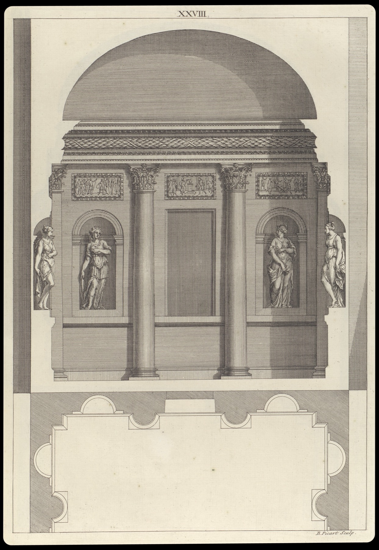
Elevation, section and the building's thickness
An elevation removes perspective distortion from a projected face so that bays, openings, roof profile and exterior rhythm can be compared. It is strong at describing the ordering of a facade. It is weak at conveying what a deep wall, hidden courtyard or unequal interior level does behind it. Even an apparently symmetrical elevation can conceal an asymmetric plan. The absence of foreshortening helps a measured record, but it does not mean the building was ever viewed from an impossible perfectly level position. The projection is an analytical decision. [8], [11]
A section chooses a vertical cut through the structure. It can reveal wall and slab thickness, interior heights, the relation of roof to room, a buried storey or a stair's landing. A different cut might reveal different evidence. That is why a section line on a plan and a matching reference on the section matter. Paul Rudolph's perspectival sections, discussed by the Metropolitan Museum, deliberately combine the cut with depth and interior sequence. They are compelling hybrid images, particularly for complicated volumes; they are not equivalent to a reliably dimensioned measured section in which scale and material observation govern every line. A section may describe structural reality, spatial aspiration or experience according to the particular sheet's function. [8], [13]
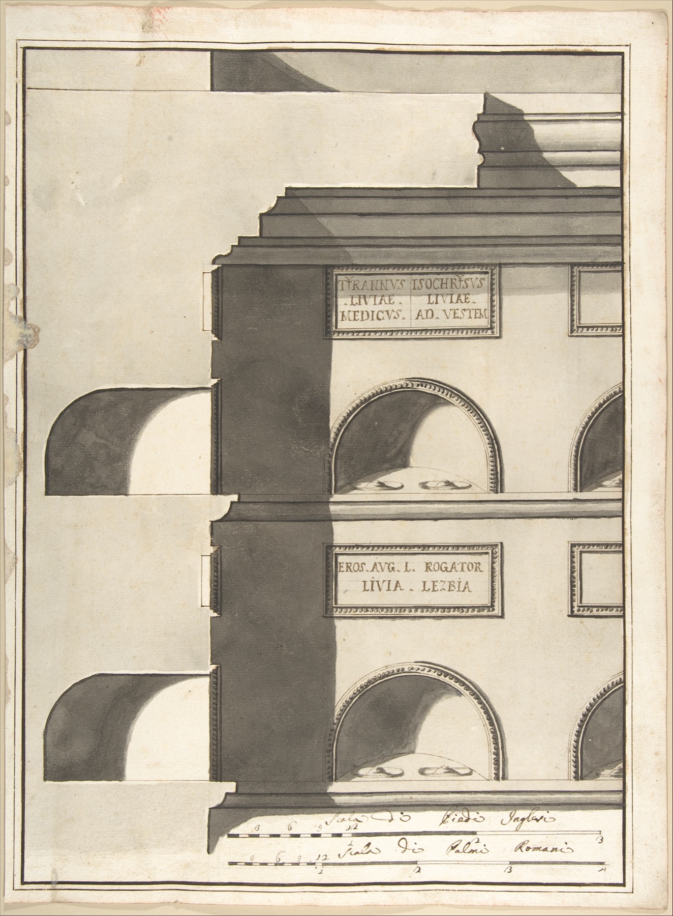
Sections also expose a temporal problem. A restoration drawing might cut through a proposed reconstruction of a lost roof. A HABS survey might cut through the roof as found in the twentieth or twenty-first century. A drawing that merges both into one crisp silhouette can be educational, but only if the differing source layers are identified. The National Park Service requires that interpreted previous phases on heritage sheets cite the evidence on which they rest. Historic Pantheon drawings demonstrate how even learned reconstructions can idealize and omit portions of built fabric. The distinction is not intended to diminish historical drawings: it makes their ingenuity and their limitations visible. [8], [22]

Text alternative for the diagram
The invented proposed section includes a stair and one roof profile. The later survey shows a different roof and no stair. A difference can record actual alteration rather than an error, while earlier inferred phases must cite evidence.
Perspective, axonometric and the experience of a place
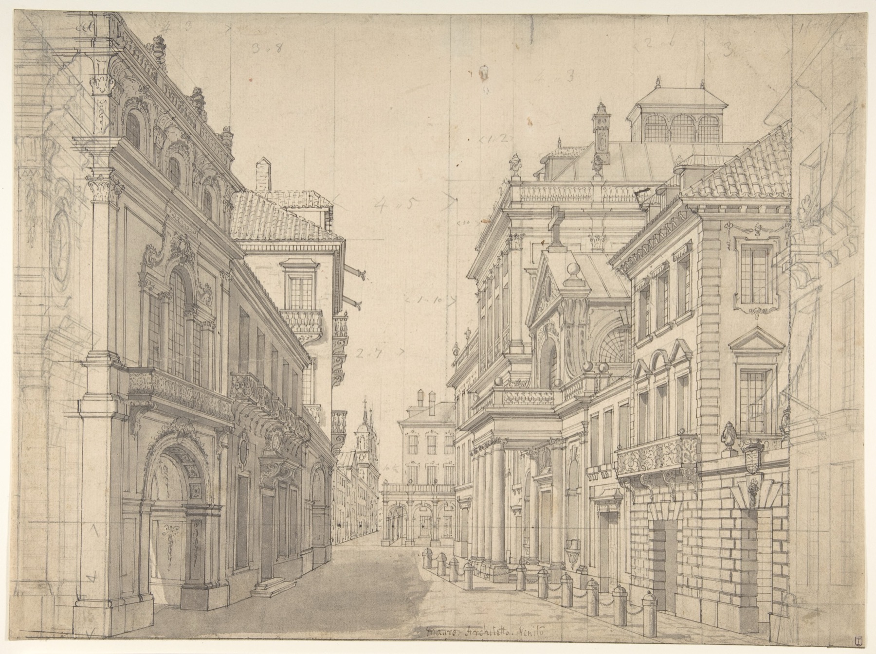
Perspective can make a doorway feel inviting, a nave long, or a high room dramatic by mimicking depth from a particular eye position. Its strength is narrative: it suggests what a person may encounter. It also selects that person and that place to stand. A high, empty eye-point can erase ordinary crowding; a low view can make a proposal grander; lighting may suggest materials never specified. These are not reasons to discard perspective. They are reasons to ask whether the image claims a viewpoint, a design intention, a future scenario or a measured fact. The publisher account of Pérez-Gómez and Pelletier's work underlines that perspective's authority has been historically debated, rather than arising as a simple “true” solution to all architectural questions. [12], [27]
An axonometric view follows a different logic. It projects three directions under consistent rules, often letting a viewer inspect several faces and a plan-like relationship at once without perspective convergence. It can be exploded to separate roof, frame and rooms, or cut away to show an interior. A HABS axonometric may be scaled along its axes; HABS guidance generally avoids perspective for the reliably dimensioned measured record. A drawing of this kind still selects which components to remove or foreground, so its apparent objectivity must not be mistaken for photographic completeness. For a complex junction it might be more instructive than a realistic rendering, while for the lived experience of entering a building it may be less immediate. [8]
Physical models can think, test and persuade
The small building-like object in a gallery is easy to mistake for a miniature of something already determined. Some models are that; others are studies through which masses are shifted, openings tried and material resistance felt. A white volume can isolate outline and shadow but conceal material and structural questions. A sectional model can expose a stair or roof, while a site model lets topography and neighbouring buildings change the reading. A full-size prototype of a facade joint operates at still another scale: it tests making and performance instead of merely summarizing form. Matthew Mindrup frames the architectural model as sign, prototype and generative instrument; the diversity of models in the CCA and Getty archives makes the narrow “miniature” definition untenable. [2], [3], [14], [15]

Text alternative for the diagram
A model might test design geometry, evoke a sacred place, raise paper walls from a drawing, or test a joint at full size. These roles are not one mandatory history or proof that the Mahabodhi and Mezcala objects served as construction prototypes.
The model can also be an argument to someone who does not readily read a plan. One may lift a roof to view a court or rotate an object to understand an approach. Yet a model has its own rhetorical limits. A smoothed surface hides joins; a beautifully crafted scale object can suggest a certainty the design has not reached; a model photographed from one dramatic angle returns to the selectivity of a perspective. Its caption should identify scale, material, author, date, project state and whether it was a design instrument, presentation object, study for fabrication or later reconstruction. An Edo okoshi-ezu may cross the drawing/model boundary physically, but its archive purpose still requires particular evidence. [14], [17]
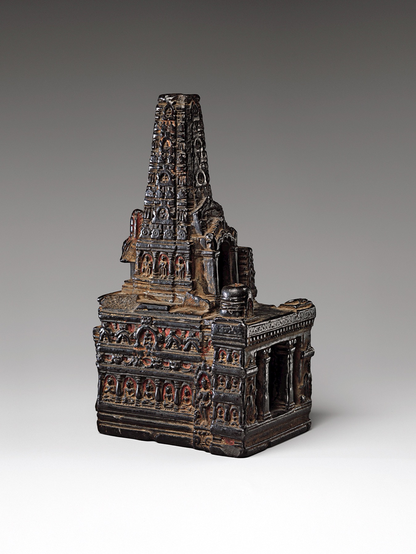
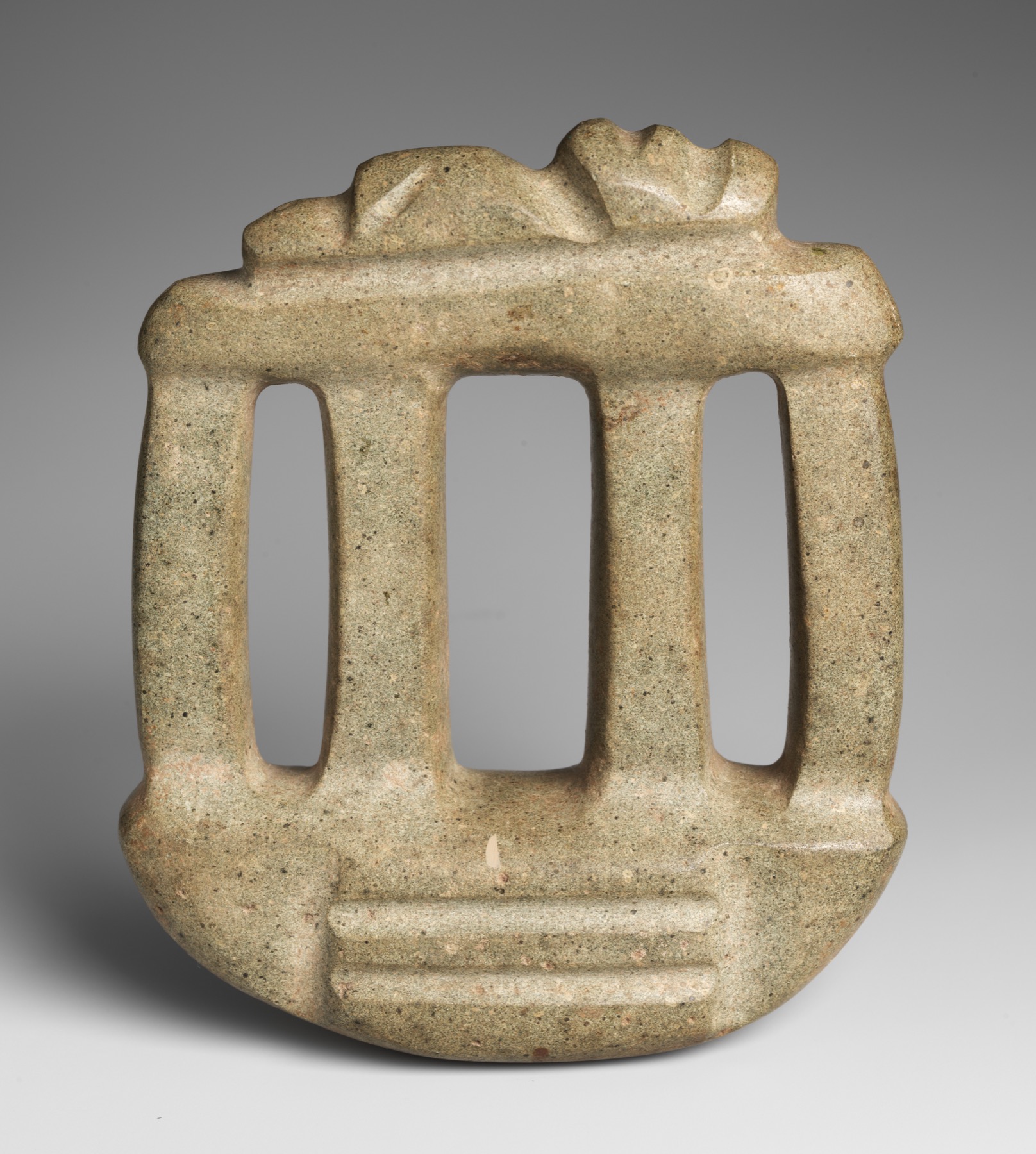
The Metropolitan Museum's twelfth-century stone model of the Mahabodhi Temple at Bodhgaya and a much earlier Mezcala greenstone architectural model make the range especially clear. The Indian miniature participates in a devotional world in which the temple and its image could be encountered at small scale; it is not a builder's tested prototype of the present building. The Mezcala object's column-like entrance may refer to architecture, but its original archaeological context and ritual purpose remain uncertain. Neither should be captioned as a “master plan” simply because it resembles a building. Such objects expand the history of representing architecture, while resisting easy conversion into documents of a construction job. [35], [36]
Digital drawing, information models and fabrication
Computer-aided drawing did not end sketching, paper or physical model-making. It offered another environment for geometric change, layered drawings and repeated coordination. A three-dimensional digital file may generate plans, sections and views, but its usefulness depends on how elements and attributes are organised, which version is being shared, and whether the team agrees on the meaning of the exchanged data. A realistic rendering is an image of one possible view; an information model is a structured description of building components and relations. The open IFC specification, maintained by buildingSMART, exists to exchange such descriptions across software and disciplines. The fact that a file follows an open schema does not prove every detail was entered accurately, that every application will read it identically, or that a designed surface is buildable. [16], [28]
The Getty's Gehry archive includes large quantities of conventional-looking drawings and models as well as evidence of a technologically changing practice. Dennis Shelden's MIT dissertation asks how digital surface representation relates to constructibility in Gehry work; that question should not be mistaken for proof that software alone built a particular facade. Curves and joints become construable when geometry, tolerances, material systems, prototypes and people are coordinated. A screen image can propose one of those things, but cannot substitute for all of them. [15], [29]

Text alternative for the diagram
A rendering selects one eye point, lighting and visible surfaces. An information model includes component identities, geometry, attributes and possible exchanges through IFC. The open format cannot guarantee that the model is complete or buildable.
Digital records pose a later archival problem as well. A sketchbook can be held and a wooden model photographed from several sides. A digital model may depend on a versioned format, external files, naming practice and software environment to reveal what its maker intended. The CCA Ábalos & Herreros fonds lists digital carriers along with sheets and models, while Kyoto's archive distinguishes modern originals and blueprints; archives document the medium of the record as part of its meaning. Even a perfect exported picture may lose the editable relationships or time-stamped decisions that mattered in the design file. Preservation therefore concerns provenance and file structure as well as visual appearance. [2], [25], [28]
Records after building: observation is not original intention
The Historic American Buildings Survey, and related engineering and landscape programmes, are examples of architecture represented for later study rather than immediate construction. A measured drawing records the building's condition when its survey is made, alongside large-format photography and written historical research. That condition may include altered openings, lost stairs, restorations, repairs and new materials. The Library of Congress is explicit that HABS sheets need not be the architect's original design sheets or the original contractor's as-builts. The National Park Service calls the survey drawing an “as-built” record of the condition at documentation time; these usages are compatible only if the date and purpose are explained. [8], [9], [10]
An archaeologist or historian may also draw a previous state from surviving evidence. Such an image can be valuable precisely because the original form is gone. It is not, however, direct observation. HABS guidance tells the drafter to cite sources on drawings that interpret earlier phases. It also warns against line patterns that present guessed masonry texture as surveyed fact, and generally avoids perspective where dimensions must remain dependable. Photography can show surface and context, drawing can select geometry, and a written account can record dates, occupants, later work and uncertainty. Together they are stronger than treating one crisp elevation as complete evidence. [8], [9]
An anonymous French sheet made in the early or middle sixteenth century studies the older Temple of Hercules at Cori with plan, elevation and details; the reverse addresses St Peter's drum. It is a record made by a later viewer studying older and contemporary architectural forms, not an original Roman construction plan. Nor is it a HABS sheet. The object clarifies a recurring archival task: the image's own date and purpose are distinct from the date of the architecture it depicts. [37]
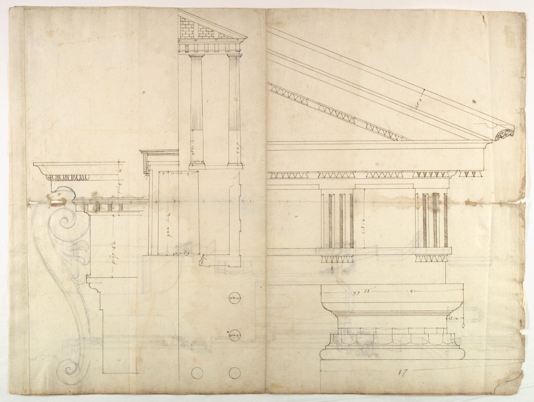
A collection catalogue adds another layer. The Getty's Frank Lloyd Wright guide includes large numbers of photographic copies rather than original sheets. The BnF's research account notes that some architectural holdings are still imperfectly catalogued. The date assigned to a scanned image could name the building, the act of drawing, the later copy or the archive's acquisition. “Original” and “copy” are material statements, not measures of quality: an old copy can carry information lost from the design original, but it should not be attributed to the wrong hand. A confident public caption has to specify what is actually known and leave an attribution uncertain when evidence does. [4], [30]

Text alternative for the diagram
A design sheet records a proposal date; a blueprint or copy has its own reproduction date; a survey records condition at the survey date; a reconstruction represents inference and should cite its source. They need not appear in one inevitable order.
Who understands a drawing?
Architectural conventions can be learned, but they are not automatically shared. A person familiar with wall weights, door arcs, hatches and scale may read a technical plan quickly; another may see almost identical lines everywhere. Soranart Sinuraibhan's University of Sheffield dissertation tested this problem through two questionnaires using plans of one residential flat. The first received 379 non-architect responses from Sheffield's university population, 41 first-year and 38 diploma architectural-student responses; the second received 482, 25 and 32 respectively. Those numbers are responses received, not necessarily complete answers to every item. The sample was self-selected and university-centred, with advanced students standing in for experienced professionals. It is evidence about these drawings and respondents, not a universal diagnosis of the public. [26]
In the first test, many non-architect respondents preferred a pictorial or three-dimensional plan at first glance, while the advanced students answered detailed questions about symbols and codes more reliably. Preference and task accuracy were not the same thing. In the second test, a relatively simple “communicative” plan D used limited colour and a circulation cue; it was judged useful on several understanding questions. A denser pictorial alternative B1 was less consistently successful, despite showing more recognizable objects. Some diploma students returned to conventional graphic details when the question demanded technical specificity. The actual comparison drawings make the reason plausible: adding sign after sign is not the same as clarifying route, room and scale. But the study does not show that plan D would best communicate every hospital, station, church or construction detail. [26]
A good public drawing may therefore carry a familiar room label, a visible scale, a plain-language key and a cut or orientation marker, and explain what the viewer cannot infer from the view. A technical drawing may need different precision, including dimensions, material notes and a linked detail. Communication does not require abandoning professional conventions; it requires acknowledging that the convention is a code, and giving the intended reader enough of the code to make the right decision. Even colour must work with text, shape or line style where readers may be colour-blind or where a copy is monochrome. The choice of graphic language is also a choice about whose questions count. [19], [26]
Images in public culture, not just at the building site
Architectural representations can acquire lives separate from a finished building. The Metropolitan Museum's Palladian book illustrates how printed designs can teach, authorize and circulate architectural ideals. The BnF's exhibitions and holdings show drawings made for learning and presentation; the CCA has examined how drawings and models move through bureaucracies, scholarship and art markets. MIT Press presents Jordan Kauffman's Drawing on Architecture as a study of drawings entering galleries and becoming collectible in the late twentieth century. This is not a claim that every drawing became art or that a gallery sheet ceased to refer to a building. It means an image can be an artifact of architectural thought, a public argument, an office document and a cultural object at different times. [4], [23], [31], [32]
An unbuilt proposal can be particularly revealing. Its spectacular image may change what other architects imagine even if it never instructed a mason. A heavily revised plan may reveal the negotiation between a client and a designer more clearly than the polished final view. A working sheet can disclose the anonymous specialist labour that the familiar “master architect” narrative hides. The CCA's critique of the autonomous author model is a useful reminder that representation passes between clients, authorities, engineers, fabricators, archivists, teachers and visitors. That social circulation is part of what architectural design language does. [19], [31]
How to read an architectural image responsibly
The most useful first move is to identify the record type. Is a plan showing existing walls, an option under consideration, a proposed construction, or the measured remains of a building? Next, find a scale, north or orientation cue, legend, drawing number, cut reference and revision date if they exist. A photograph's camera location and a model's removable pieces can matter as much as the sheet's line work. Compare the record with a second kind of evidence when possible: a section against a plan, an original proposal against a survey, a model against a construction photograph, or a diagram against a written history. The mismatches are not always mistakes. They may mark a decision changed, a building altered, an archive copied, or an earlier phase interpreted. [8], [9], [10], [19], [26]
The final question is what the representation does not establish. A plan cannot by itself prove structural feasibility; a section may omit perpendicular circulation; a polished rendering may leave materials and users indefinite; a measured survey cannot reveal every earlier design intention. In architecture, images are at once powerful and partial. Their selective nature is what allows them to make complicated relationships understandable. Their responsibility is to make the selection, purpose and evidentiary status discoverable to the people who encounter them. [8], [12], [16], [19]
Explore RELATED Artworks and Records
These surviving objects demonstrate different audiences and evidentiary roles for architectural representation.
Palladio in print
Plan and sectional image circulated through a sixteenth-century treatise.
Met Open Access object imageFrench mixed-view sheet
A single sheet holds plan, perspective and faint alternatives.
Met Open Access object imageRenaissance drawing and model study
An institutional study of combined projections, foldable sheets and later surveys.
Separate Met Open Access sheet preview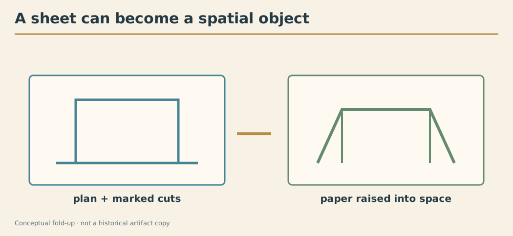
Nakai-family fold-up records
Kyoto University preserves Edo drawings that may become spatial paper objects.
Original teaching diagram preview, not archive scan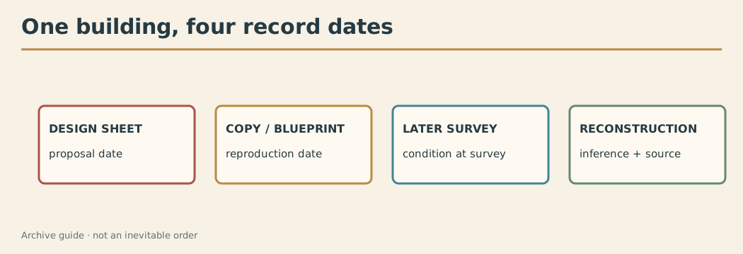
HABS measured records
Later survey records must be dated apart from original design and inferred phases.
Original teaching diagram preview, not HABS scanWatch: Drawing and Models in Practice
Two institutional moving-image resources; the schematic previews are not video frames.
Power up your creativity: New ways to draw
Audio-described, collection-inspired drawing exercise. [33]
Preview: separate original teaching diagram, not a film still.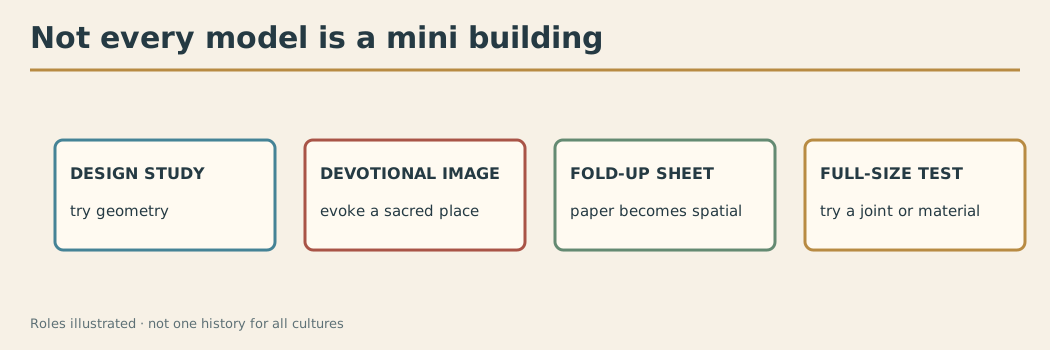
Sculpting Harmony
Archival sketches and models alongside Getty video portraits. [34]
Preview: separate original teaching diagram, not a film still.Explore Kyoto University’s Nakai-family fold-up drawing archive: a separate visual study resource, not a film. [17]
Frequently Asked Questions
No. Drawings, physical and digital models, specifications, photographs and later surveys perform different jobs. [1] [2] [8]
No. It is a coded horizontal cut that selects rooms, walls and routes without showing every height or experience. [8] [11] [26]
An elevation projects a face without perspective foreshortening; a section cuts vertically to reveal levels and thickness. [8] [11] [13]
No. It may be a proposal, stage-set image or presentation view and does not establish construction, dimensions or performance. [8] [12] [27]
No. Some are studies or tests, while others are presentation, devotional or ritual representations. [14] [35] [36]
Usually not. HABS documents condition when surveyed; original design, survey and inferred earlier phase must be identified separately. [8] [9] [10]
No. A rendering is a view; a BIM data model can hold structured geometry, elements and attributes. IFC exchange does not guarantee constructibility. [16] [28]
References
- “RIBA Collections”
- Ábalos & Herreros fonds
- Álvaro Siza archive
- “Dessins d'architecture dans les collections”; collections of drawings
- HABS/HAER/HALS documentation guidelines
- “Trazos en diálogo: Archivo de Arquitectos Mexicanos”
- archive foundation and collections description
- HABS Guidelines: Measured Drawings
- “Technical Note on Documentation”
- “Exploring Buildings by Louis I. Kahn in the Historic American Buildings Survey”
- Secretary of the Interior's documentation standards
- “Italian Renaissance Architectural Drawings”
- “Paul Rudolph: Laying New Foundations”
- Matthew Mindrup, The Architectural Model
- Frank Gehry archive
- IFC technical standard; IFC 4.3 scope
- Nakai-family architectural records and okoshi-ezu
- Josiah Conder architectural drawings digitisation
- “Quality Control for the Preparation of Working Drawings”
- RIBA Plan of Work 2020; one-page stage PDF
- “Special Problems in Architectural Design”
- “Drawings of the Pantheon in the Goldschmidt Scrapbook”
- Andrea Palladio, I quattro libri dell'architettura, object record
- anonymous French architectural drawing, c.1650–70
- Masuda Tomoya originals, blueprints and work records
- Draw the Line (University of Sheffield doctoral thesis, 2005)
- Alberto Pérez-Gómez and Louise Pelletier, Architectural Representation and the Perspective Hinge
- architectural computation research overview
- Dennis Shelden, “Digital Surface Representation and the Constructibility of Gehry's Architecture”
- Frank Lloyd Wright finding guide; research policy 2020
- Architecture Itself and Other Postmodernist Myths
- Jordan Kauffman, Drawing on Architecture
- adult learning and audio-described “Power up your creativity” video
- Sculpting Harmony online exhibition and video portraits
- Model of the Mahabodhi Temple, twelfth century
- Mezcala architectural model
- Temple of Hercules, Cori, plans and elevations in the Goldschmidt Scrapbook
Explore RELATED Architecture
These built-place pages show why plans, perspective, photographs and later records must be read together.
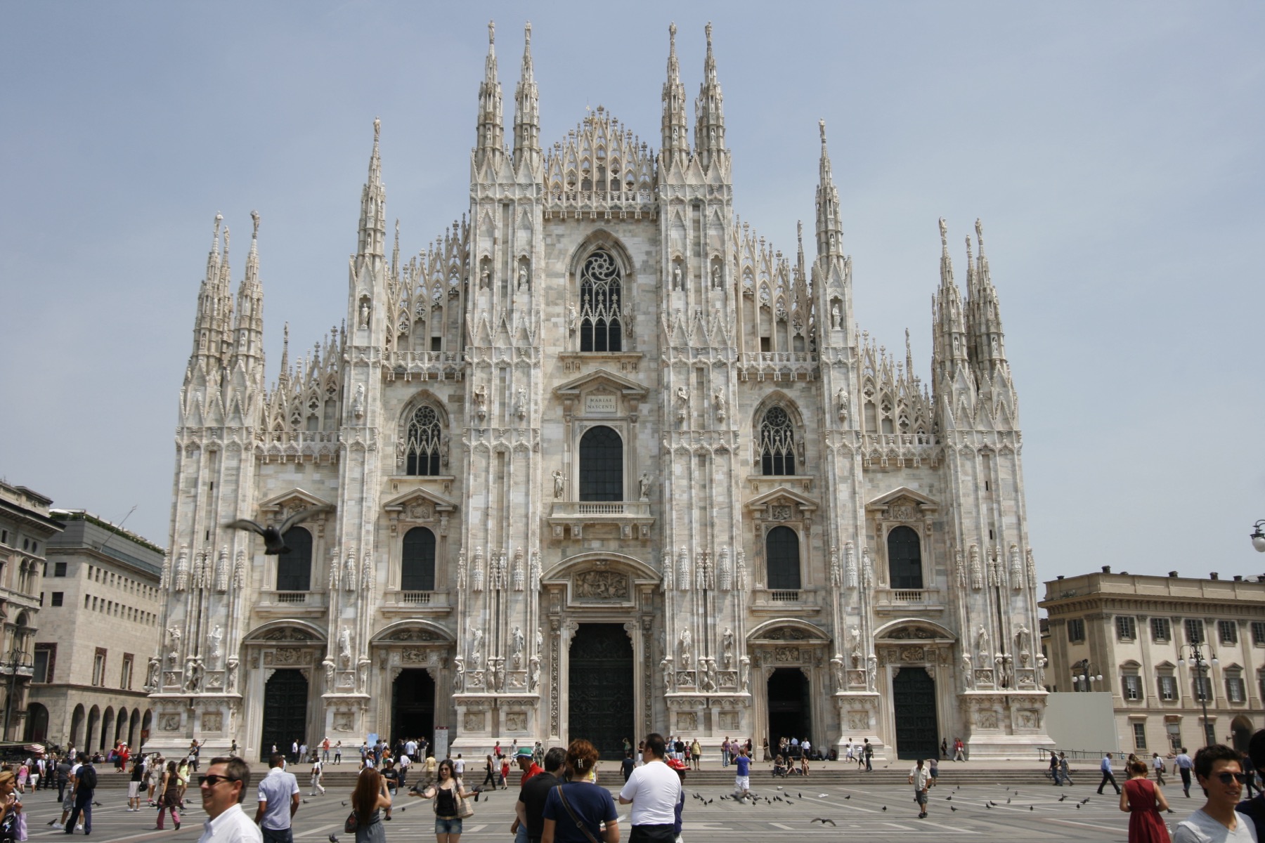
Milan Cathedral
Design and geometry changed through argument and building.
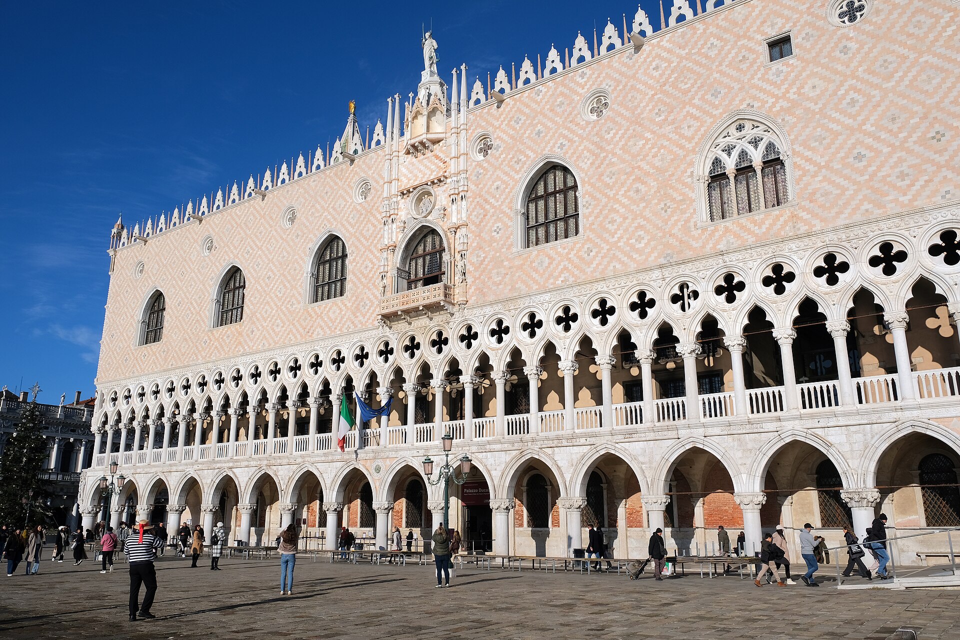
Doge's Palace
A facade conceals a long sequence of alterations and uses.
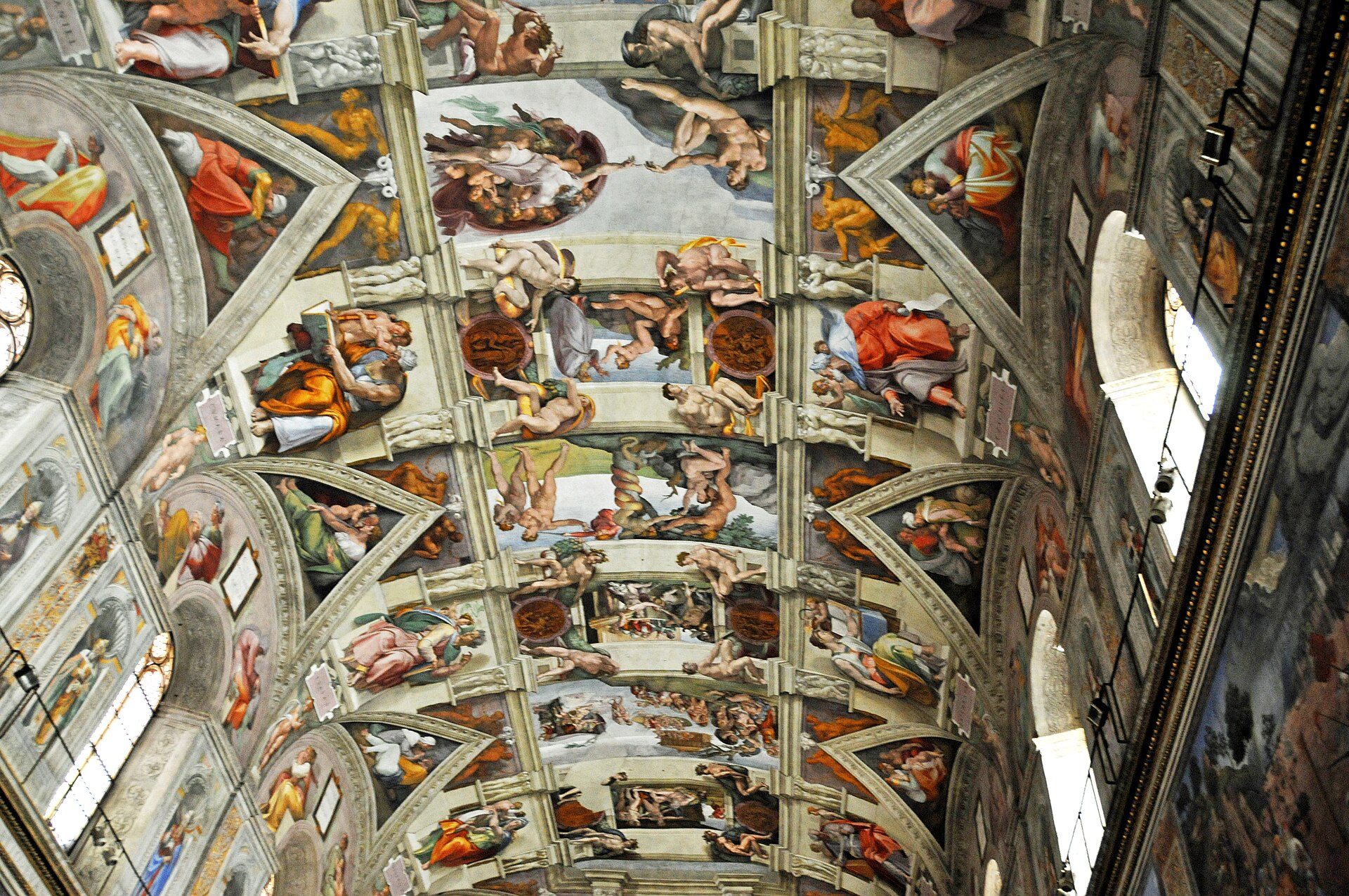
Sistine Chapel
Architectural fabric and painted programmes have different records.

Borobudur
Plan and visitor sequence reveal different spatial relations.

Machu Picchu
Ruins and later surveys mediate the reading of built terraces.
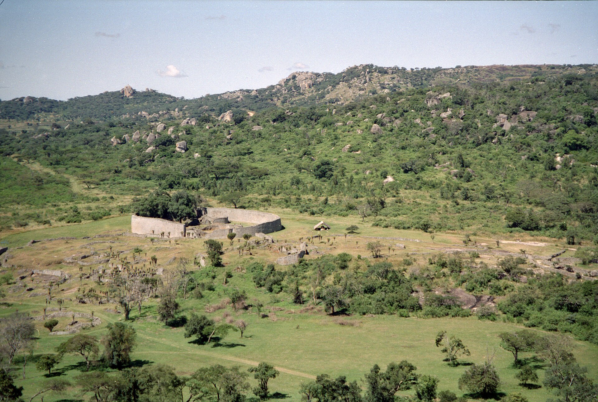
Great Zimbabwe
Heritage records must distinguish fabric from later inference.
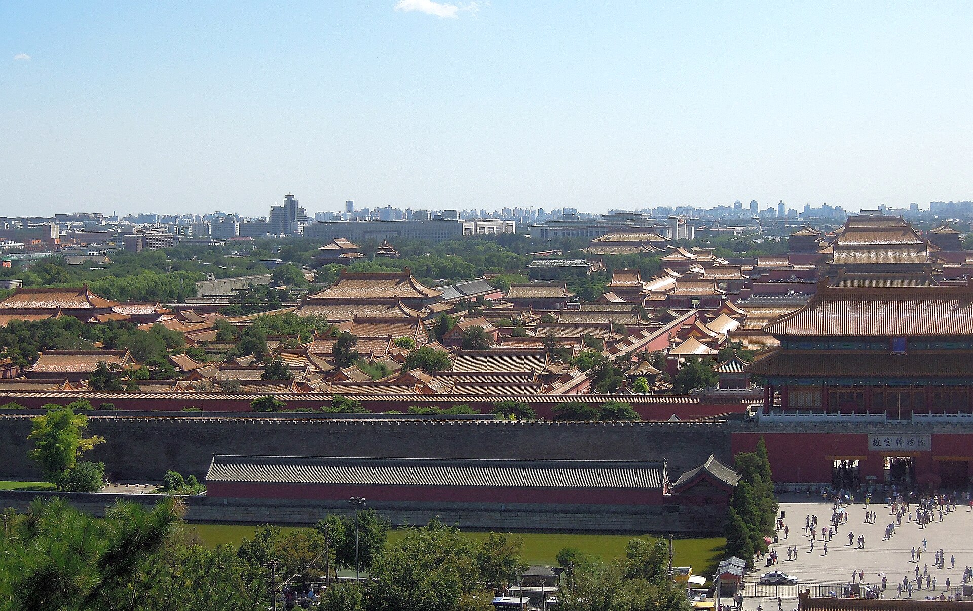
Forbidden City
Palace plans and surviving courts changed across reigns.

Teotihuacan
Archaeological plan and exposed monuments are not the whole city.