


 by Tom Gurney
Tom Gurney BSc (Hons) is an art history expert with over 20 years experience
Email: tomgurney1@gmail.com / Phone: +44 7429 011000
Projection, Building and Evidence
An axonometric drawing turns a building so that several of its faces and spatial relationships can be understood on one flat sheet. Unlike an ordinary perspective view, parallel directions do not converge toward vanishing points and a distant wing does not become smaller merely because it lies farther away. That consistency makes the view especially useful when an architect needs to relate floors to walls, a roof frame to supports, or a museum gallery to the archaeological ground beneath it. It does not make the drawing a complete description of the building. The chosen angle, cut surfaces, omissions and graphic emphases determine what is visible and what remains unknown. [1], [2], [3], [4]
There is a naming complication worth understanding before reading any example. In technical descriptive geometry, an axonometric is an orthographic parallel projection viewed obliquely to the three principal planes; isometric, dimetric and trimetric are its families. Architects also use “axonometric” for plan-oblique or military drawings, whose projectors are oblique rather than perpendicular to the picture plane. The two traditions overlap in appearance but not in what is geometrically undistorted. A true plan-oblique retains the shape of the horizontal plan while lifting heights; an isometric view treats three principal axes symmetrically but foreshortens them. The projection type, not the umbrella term, determines which dimensions can be read directly. [1], [2], [24]
Historical axonometrics are not all designs awaiting construction. A Russian eighteenth-century city survey, Auguste Choisy's analytical reconstruction of a medieval church, a De Stijl unbuilt villa, Rafael Moneo's working museum sheet, and a recent U.S. measured-survey drawing each have a different evidential status. The most rewarding way to read them is to ask what kind of object each sheet is, which relations its projection clarifies, and what companion plan, section, photograph or archival record it still needs. [5], [6], [9], [10], [14], [15], [19], [20], [21], [22], [23]
At a Glance
- Core geometryParallel spatial directions remain parallel on the paper; recession does not itself reduce the scale of a distant part. Not every oblique line shows true length. [1], [2], [3]
- Technical familyIsometric, dimetric and trimetric are orthographic axonometric types distinguished by their treatment of three coordinate axes. Isometric is one member, not a synonym for every architectural axo. [1]
- Architectural vocabularyPlan-oblique and elevation-oblique views are often also called axonometric; the preserved plan or elevation is a different geometric promise from that of an orthographic isometric. [2], [24]
- Useful operationsCut away a wall or floor, separate layers in an exploded view, show a structural frame, or place a building in relation to site and circulation. Identify what was deliberately removed. [4], [14], [17], [18], [19], [20], [21], [22]
- Historic usesUrban survey, constructive analysis, avant-garde design argument, office working drawing, exhibition sheet and measured documentation are different categories, not one continuous design phase. [5], [6], [9], [10], [14], [19], [20], [21], [22], [23]
- What it explains wellRelations among levels, supports, rooms, roofs, material junctions and repeated structural bays, if the drawing's axes and cuts are clear. [6], [7], [14], [18], [19], [20], [21], [22]
- What it cannot prove aloneExact off-axis length, buildable joint specification, accessible route, actual light and comfort, an occupant's experience, project authorship or the condition of a building today. [3], [14], [20], [21], [22], [23], [24]
- Best companion evidenceDimensioned plans and sections, detail drawings, dated project records, photographs, and a clear distinction between proposal, construction-stage view and later survey. [3], [4], [14], [17], [18], [19], [20], [21], [22], [23]
Contents
- Geometry: the useful consistency and its limits
- Isometric, plan-oblique and other choices
- A city before Choisy: the St Petersburg survey
- Choisy's underside: construction rather than a visitor's view
- De Stijl, Proun and the artistic pressure on exactness
- Grid, part and whole—and the almost flat axonometric
- Two Mérida drawings, two architectural questions
- From a picturesque mass to a constructive section
- Survey drawings: a building recorded after design
- Cutaway, stair and the ethics of what a drawing leaves out
- Three spans, three trusses, and a bridge that is gone
- Exploded layers and drawings at different project phases
- The moving axonometric and the digital model
- Reading the sheet as evidence, not as total architecture
Geometry: the useful consistency and its limits
A building has three spatial directions that architects usually call width, depth and height. A parallel projection maps them to directions on a sheet without making a long wall's parallel edges meet at a vanishing point. This is the main visual departure from perspective. It is also why a roof truss drawn behind another truss need not shrink in the image: their differences can be compared without the optical reduction that helps perspective feel like a view from a person's eye. A plan and an elevation are also parallel projections, but they flatten most of the third dimension; an angled axonometric allows more than one face or level to appear at once. [1], [2]

Text alternative for the diagram
Three parallel edge pairs are contrasted with three receding edge pairs meeting a single point; invented geometry, not an archive object.
Consistency is not the same as universal measurability. In an orthographic axonometric, lengths parallel to a principal axis are reduced according to that axis's projection factor. A line at another angle may have a different reduction, and a curve becomes a shape that must be constructed rather than measured as a circle on the paper. Even in the architectural plan-oblique convention, where the horizontal plan is undistorted, vertical rise and slanting edges need their own stated scale or construction. A professional can recover dimensions from a known projection and data; a casual reader cannot safely take a ruler to any unlabeled diagonal. [1], [2], [3], [24]
This explains why a useful axonometric should not replace a dimensioned drawing set. The University of Rochester's fabrication advice uses an axonometric to make the object intelligible as a whole but expects orthographic views and dimensions for manufacture. Buildings multiply that need: wall thickness, connection size, levels, door clearances and tolerances require drawings that locate and specify them. CUNY's architectural drawing teaching similarly distinguishes the many relations a cutaway view can reveal from the precise information plans, sections and elevations carry. A German-language architecture curriculum at Hochschule Campus Wien teaches orthographic plans and sections alongside axonometry and central perspective as distinct representational tools. An axo is an effective bridge between views, not a magic substitute for the other views. [3], [4], [27]
Isometric, plan-oblique and other choices
The technical names isometric, dimetric and trimetric describe how three main axes are foreshortened. In a strict isometric projection they are treated equally; in dimetric two have the same treatment; in trimetric all three differ. The geometry of isometric views deserves its own detailed guide, but its practical point here is that a familiar three-faced cube does not disclose every architectural relation equally. A symmetrical box may be easy to compare; a deep site or a long gallery can become crowded, while a desired horizontal plan geometry is slanted and foreshortened. [1], [2]

Text alternative for the diagram
Three invented axis triads compare equal, two equal and three different scale factors.
Plan-oblique, also called military projection in European architectural literature, starts from an undistorted plan and extends heights at a chosen angle. It can make a plan's streets, parcels, courts and room outlines legible while still depicting façades and roof lines. The Columbia GSAPP drawing tutorial contrasts this with an elevation-oblique view, which privileges a façade instead. Both keep parallel edges parallel, yet they preserve different faces. A school design, for instance, might need a plan-oblique when its courtyards and routes matter most; a façade construction study might prefer an elevation-oblique that makes panel arrangements easier to inspect. The title “axonometric” alone does not say which promise the sheet makes. [2], [24]

Text alternative for the diagram
An invented isometric solid sits beside a rectangular preserved plan with lifted height lines.
The angle of view also establishes an argument. Looking from above makes ground, entrances, paving and the relationships among neighbouring structures readily visible. Looking from below, often called a worm's-eye view, privileges the underside of vaults or roof slabs and the relation between their supports and the space enclosed beneath them. Cuts can make hidden rooms or construction layers visible in either direction. None of these views is a normal optical position occupied by a visitor; each is a calculated transformation that sacrifices some ordinary appearance in order to reveal another relation. [6], [7], [8], [14]
A city before Choisy: the St Petersburg survey
An excerpt from a 1765–73 axonometric plan of St Petersburg records affluent residential parcels near the Catherine Canal and Bolshaya Sadovaya Street. It is attributed to a survey team including P. de Saint-Hilaire, I. Sokolov and A. Gorikhvostov. On the scan, roofs line up with courts and garden plots; individual houses can be understood as parts of a street and canal district rather than isolated volumes. The drawing concerns the city as a system of plots, access and property, a task different from rendering a single architect's future masterpiece. [23]
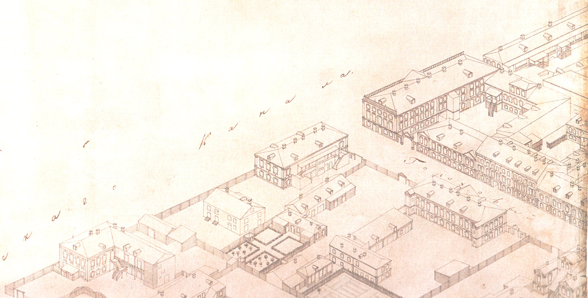
Its date matters because it precedes the nineteenth-century work of Auguste Choisy. Choisy did not invent the possibility of parallel-looking architectural views. Such views had multiple histories and purposes before his enormously influential constructive analyses. The Russian sheet does not establish that he saw or borrowed this particular plan. It shows instead why “the history of axonometry” must not be compressed into a single French origin story: an eighteenth-century urban survey could use a lifted view to make dense property relations intelligible long before Choisy's archaeological and engineering inquiries. [5], [6], [23]
The scan also exposes an axonometric's limits. It can show the spaces enclosed behind façades and where parcels adjoin, but not the interiors of all houses, the obligations of their occupants or the later changes to the district. A plan of this kind is evidence of an urban record and its method of display. It is not automatically a complete census of the people and labour within the blocks, nor proof that every line in the surviving excerpt was measured to current survey standards. [23]

Text alternative for the diagram
Four invented roofed parcels, inner yards and a street strip demonstrate parcel-scale relations.
Choisy's underside: construction rather than a visitor's view
Auguste Choisy trained and worked as an engineer while writing architectural history. His Histoire de l’architecture appeared in 1899, after earlier studies of Roman and Byzantine building. His distinctive cut, bottom-up views do not simply reproduce what an onlooker would see from the floor. They select bays, remove enclosing material and turn the structure so that the space below a vault and the masonry that produces it may be read together. French institutional scholarship places this analytical habit in his broader attempt to explain architecture through systems of building rather than through stylistic appearance alone. [5], [6], [7], [8]
In his drawing of the nave at Saint-Philibert, Tournus, cut masonry is hatched heavily; parallel arch and pier relations remain visible while the underside of the vaulted construction rises above the viewer's improbable position. The one sheet tells us how repeated supports form a spatial sequence and where massive material closes it. It does not tell us the full outward profile, the lit experience of a worshipper, or the exact material condition of the church today. It is a nineteenth-century historical reconstruction of an earlier building, not a present-day measured fabrication document. [6], [7], [8]
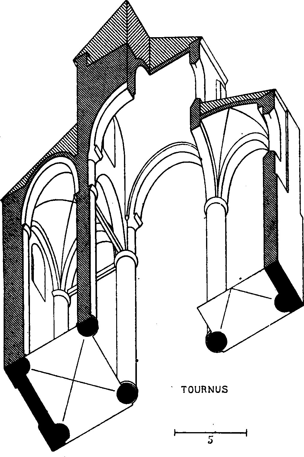
Spanish researchers Patricia Sabín-Díaz and Enrique M. Blanco-Lorenzo describe Choisy's bottom-up section of Hagia Sophia as a way to bring plan, vertical cut and vaulted volume into one analytical image. They also recognize the objection that such abstraction fails to establish the building's ordinary appearance. That is the drawing's genuine bargain: it makes an argument about spatial and constructive relationships with striking economy, but removes the viewing body and parts of the site. If a guide treats the result as an unmediated photograph of the building, it defeats the very reason Choisy chose the projection. [7]

Text alternative for the diagram
A made-up cut vault bay shows arches, support points and hatched material from an improbable lower viewpoint; no Choisy tracing.
De Stijl, Proun and the artistic pressure on exactness
The same non-optical geometry served very different early twentieth-century ambitions. In 1923 Theo van Doesburg and Cornelis van Eesteren jointly developed Maison Particulière for the De Stijl exhibition in Paris, presenting models and drawings of an unbuilt house. The Nieuwe Instituut's archive account calls its axonometric both a design exploration and a public demonstration of a more universal spatial order. A vivid sheet rendered by Van Doesburg can be attributed to his hand without assigning the whole building design to him alone. Colour blocks and interlocking planes express a proposed relation between art and architecture; they are not evidence that the house stood on a street. [9], [10], [11]

Text alternative for the diagram
Four shifted polygonal planes and an axis line illustrate composition, not a reproduction of De Stijl or Proun objects.
El Lissitzky's Proun compositions similarly give constructed forms a suspended, changeable orientation. MoMA's account of Proun 19D follows the work through changing display and interpretation. The page can be read as an exploration of spatial relations that resemble architectural volumes, but it is not a dimensioned plan for a specific building. The ability of parallel geometry to flip foreground and background is productive in such an artwork; it also warns against assuming that a plausible-looking architectural axo has a single physically reconstructible view. [12]
Research in Japanese by Michio Kato brings a further warning from Yakov Chernikhov's Architectural Fantasies. Kato's published abstract reports both perspective and axonometric images, many unusual axis arrangements beyond standard cavalier, military or isometric recipes, and a mismatch between scale inferred from axes and from drawn curves. His proposed explanation—that principal directions may have received independently chosen reductions—is cautious. These are studies of imaginative images, not a licence to declare every Chernikhov drawing geometrically false. They do demonstrate that the expressive ambition of an architect or artist may matter more to a particular sheet than strict reconstruction by a ruler. [13]
The Spanish study reads De Stijl, Le Corbusier and later constructive drawing as parts of a broad architectural conversation, but that is a retrospective interpretation, not proof of a direct unbroken line from Choisy through every artist. The archive objects themselves clarify the distinction. A Choisy cut seeks to explain an already-existing vault; a De Stijl projection helps argue for a proposed world; a Proun rearranges a visual field without asking a contractor to build it. Common parallel-looking lines do not make their evidential aims identical. [7], [9], [10], [11], [12], [13]
Grid, part and whole—and the almost flat axonometric
The Nieuwe Instituut identifies a different use of axonometric drawing in Dutch Structuralism. The 1950s–60s interest in grids, repeatable parts and extendible wholes made a view that could display many connected units especially attractive. An axo can show how one room cell belongs to a larger field or how a street-like interior branches through it. These drawings propose spatial and social order but do not measure how residents actually occupied every threshold. Grid geometry is an explanation of relation, not a completed account of life in the structure. [9]
John Hejduk's Diamond Series pushed against the idea that an axonometric must show three readily readable faces. In architect Stan Allen's first-person account of Hejduk's 90-degree method, plan and front are effectively hinged into an almost flat image, while side depth collapses. The resulting ambiguity was part of a deliberately architectural and painterly experiment. The diamond houses in this discussion were drawing projects; their paper presentation must not be written as documentation of constructed dwellings. A projection's awkwardness may be intentional when the designer wants a viewer to confront the relation between flat composition and spatial object. [16]

Text alternative for the diagram
The side receding axis of an invented prism is made nearly flat beside an ordinary three-face prism.
Collection records can also name a drawing's stage. The Canadian Centre for Architecture catalogues an axonometric of Alison and Peter Smithson's House of the Future as a final scheme for the 1956 exhibition, not the first conception of the project. A later CCA exploded axonometric associated with an Eisenman/Robertson 1986 Parc de la Villette proposal belongs to an unbuilt competition entry. Both reveal possibilities of architectural communication, but neither should be captioned as an executed building or an origin sketch. [17], [18]
Two Mérida drawings, two architectural questions
Rafael Moneo's National Museum of Roman Art at Mérida brings the distinctions into one office. The project began in 1980, was completed in 1985 and opened in 1986. The studio had to build a contemporary museum above dense archaeological remains and along a present-day street. Moneo's own account describes a choice between ancient orientations and the current urban line, with the latter governing the new building. A serial structure of brick cross-walls and arches had to become a finite public institution on that constrained site, while respecting and admitting access to the excavated layer below. [14], [15]
The first of two sectioned axonometrics was drawn in September 1980 by architect Enrique de Teresa during detailed design. In Stan Allen's account, this bird's-eye sheet was a working drawing. It holds archaeology, retaining wall, exterior street, varying levels and overhead structure in a single field. A buttress midway between regular cross-walls serves both a lower retaining wall and a higher street wall; nearby openings and indirect light belong to the same architectural problem. The cuts do not just show an attractive brick volume. They expose how a public museum can reconcile a structural rhythm with the irregular urban edge and the remains beneath it. [14], [15]

Text alternative for the diagram
An invented museum layer stands over a green excavation zone and stylised arch traces; no Moneo office sheet is copied.
The second sheet, made by Stan Allen in May 1984, views Mérida from below. His account remembers Moneo setting that worm's-eye direction, and a dialogue over what to cut and stress. The view emphasizes the underside of arches, skylights, concrete bridges and the outfitting needed to make the brick structure a museum. It can describe the overhead enclosure and the way elevated passages thread through thick walls in a manner a simple ground plan cannot. It also gives up the street and the archaeological remains as visible context. Allen is candid that he does not remember the exact commission for the sheet and estimates, rather than certifies, how many days it took. [14]

Text alternative for the diagram
An invented upper slab and underside arches leave street and ground out of view; no Allen original is copied.
Moneo later asked that roughly 10–15 centimetres be cut from one side of Allen's drawing. Cropping reduced the impression of a free-floating architectural object and shifted attention toward the interior that runs beyond the paper's edges. Allen observes that a pre-crop photograph of the more spectacular view circulated widely. A reproduced image can therefore document an intermediate sheet state, not the architect's final choice of frame. This is an archival fact about a physical drawing and a design judgement about representation: the angle and the edge of paper both shape what building a viewer thinks it sees. [14]
Rosamund Diamond's study of drawing types, in a Leuven University Press collection, treats Mérida's cutaway as an example of a drawing that can be simultaneously exploratory and communicative. Allen's earlier/later distinction makes that point concrete. The 1980 view helped work out detailed relations before construction; the 1984 view clarified another reading for a public audience. Neither is interchangeable with the other, and neither cancels the need to observe the actual museum and its site. [14], [15], [25]
From a picturesque mass to a constructive section
An axonometric of a building can be little more than an appealing raised footprint. Constructive axonometrics make a different demand: walls, windows, insulation, frame, fasteners or roof layers must be distinguished so that the viewer understands how a form is supported and assembled. This distinction became important in late twentieth-century architectural publishing. Sabín-Díaz and Blanco-Lorenzo contrast merely descriptive volume views with analytic drawings of material junctions, prefabricated elements and assembly. Their Spanish history moves from James Stirling's various projection types and Moneo's sectional cutaways to Edward R. Ford's comparative studies of modern building details and the magazine Tectónica. The argument is about what the drawing chooses to reveal, not a claim that one projection automatically makes a design buildable. [7]
Ford's The Details of Modern Architecture, volume 1, appeared in 1990. The Spanish authors read its sectional and axonometric details as a comparative way of examining the relation between material arrangement and architectural character. A window corner or wall-to-roof joint can be presented with enough surrounding construction to make a tiny component intelligible as part of a building. Such a drawing carries a different scale of thought from a De Stijl villa floating in empty paper space. It does not eliminate specifications or site inspection, but it asks readers to understand the chosen materials rather than admire only a finished silhouette. [7], [29]
The first Tectónica monograph appeared in 1996. The publication's own account identifies constructive axonometrics as central to its explanatory work. An opening around a window can show weathering, structural support, finish and the meeting of materials in a view that cuts through the wall; linked plans and construction details supply dimensions and further confirmation. The Spanish university researchers describe examples in which a drawing was redrafted to resolve what plans, execution documents and built photographs showed differently. The result is not simply a promotional image of a project. It is a claim about its material system, one that can be interrogated beside the actual building and its written construction record. [7], [28]

Text alternative for the diagram
Five invented wall plates separate exterior finish, air gap, frame, insulation and lining.
The A Coruña teaching examples in that study include a 2014 tower structure and 2015 roof-frame proposal. Their axonometrics aim to separate elements and communicate assembly, sometimes at building scale and sometimes at component scale. These are student works and the researchers' account of local pedagogy; they do not establish an independent causal measurement that every student who draws an axo builds better. What can be seen more securely is a change in what the sheet depicts. A roof is no longer only a surface above a plan; its beams, coverings and sequence of joining become the subject of the drawing. [7]

Text alternative for the diagram
Four lifted roof layers show cover, battens, membrane and truss, not actual construction gaps.
Survey drawings: a building recorded after design
Some of the clearest surviving axonometric sheets were made after a building existed. The Historic American Buildings Survey and Historic American Engineering Record use measured drawings, photographs and written histories to record buildings and structures. Their axonometric sheets are therefore generally not the architect's original design instructions. This changes the questions a reader can ask. A survey view can bring inaccessible structure or room relations into one image; the historian still needs to know its date, how it was measured, what changes occurred before that date and which aspects were left outside the drawing. [19], [20], [21], [22]
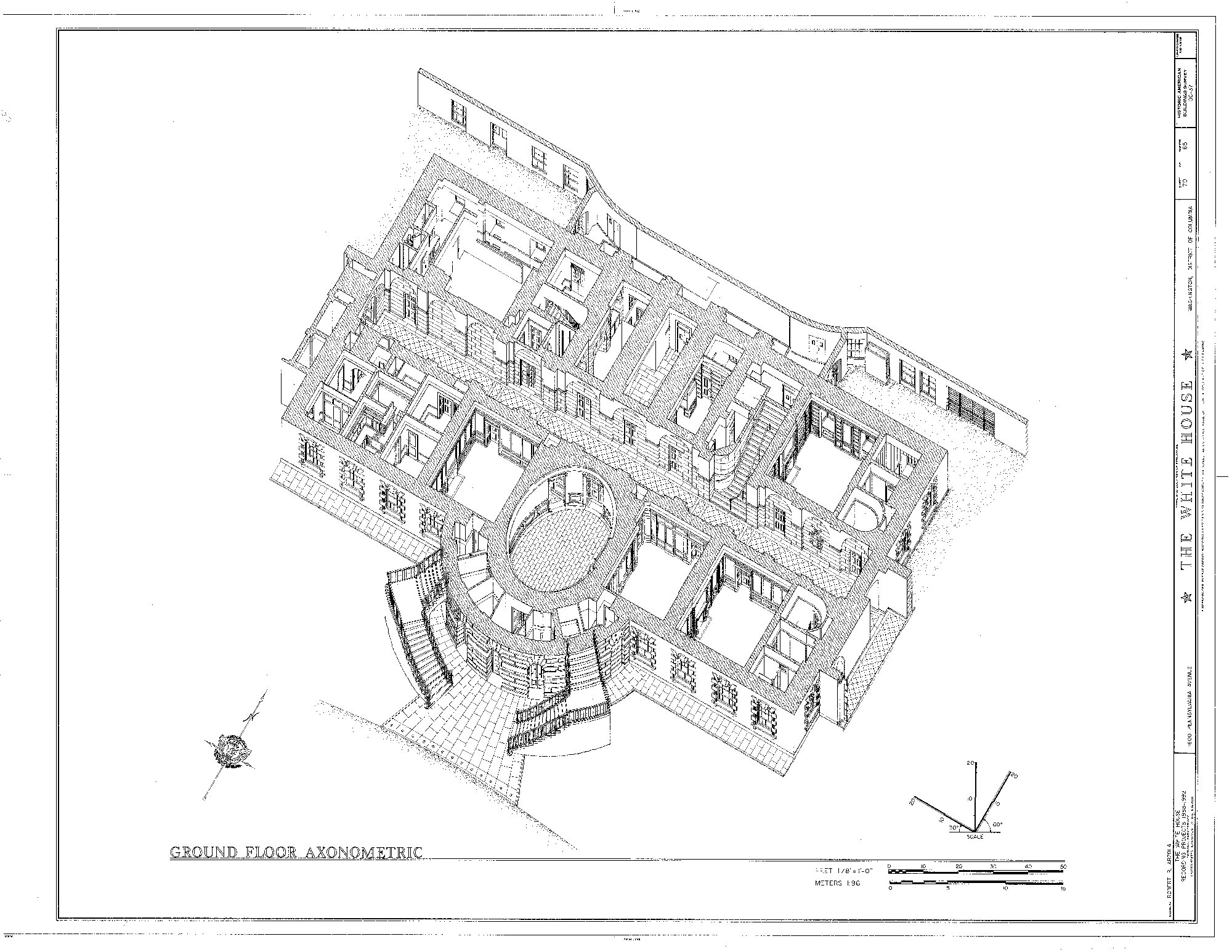
The 1992 HABS ground-floor axonometric of the White House cuts away upper enclosure and lets the reader see room divisions, stairs and the curved frontage together. The drawing is labelled ground-floor axonometric and belongs to a large HABS series. It is neither James Hoban's original proposal nor a statement about the building's present-day access or security arrangements. What it provides is a historically dated analytical arrangement of a famous building, with a spatial breadth difficult to communicate in a single frontal photograph. Its partial cut must be read beside the plans, sections and historical records in the survey rather than treated as the whole history of the White House. [19]
The HABS survey of the St Elizabeths Hospital Cow Barn makes a different kind of relation visible. Gregoire Holeyman's 2005 timber-framing axonometric removes most cladding and shows a long repeated skeleton of posts, roof members and diagonals. A photograph by James W. Rosenthal from the same documentation sees a particular upper-level corner from within: timber surfaces, bracing, sheathing and the actual density of the joints return to the abstract lines. The drawing clarifies the large frame; the photograph restores one place within it. Neither alone specifies all the connections or the uses of the dairy building. [20]
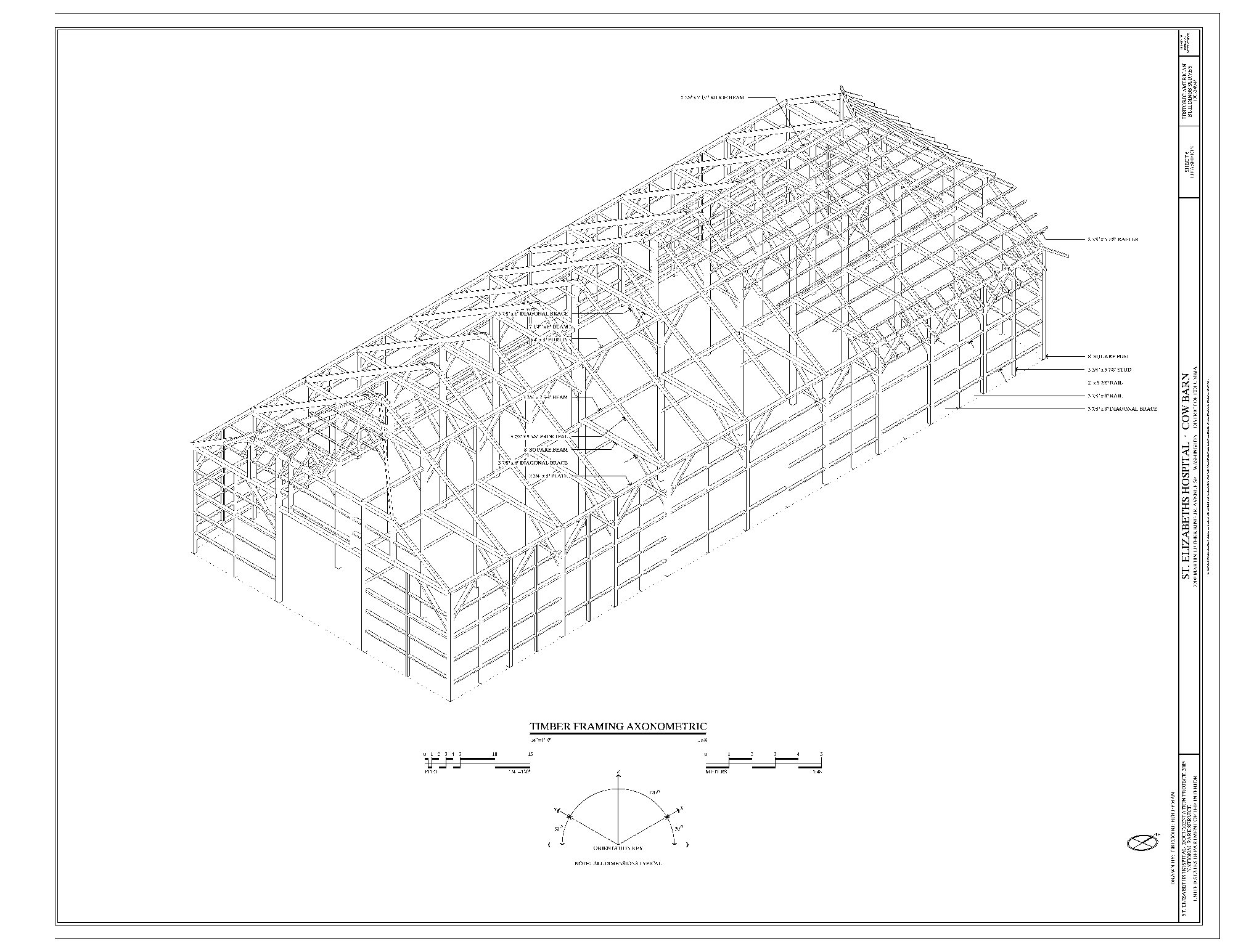
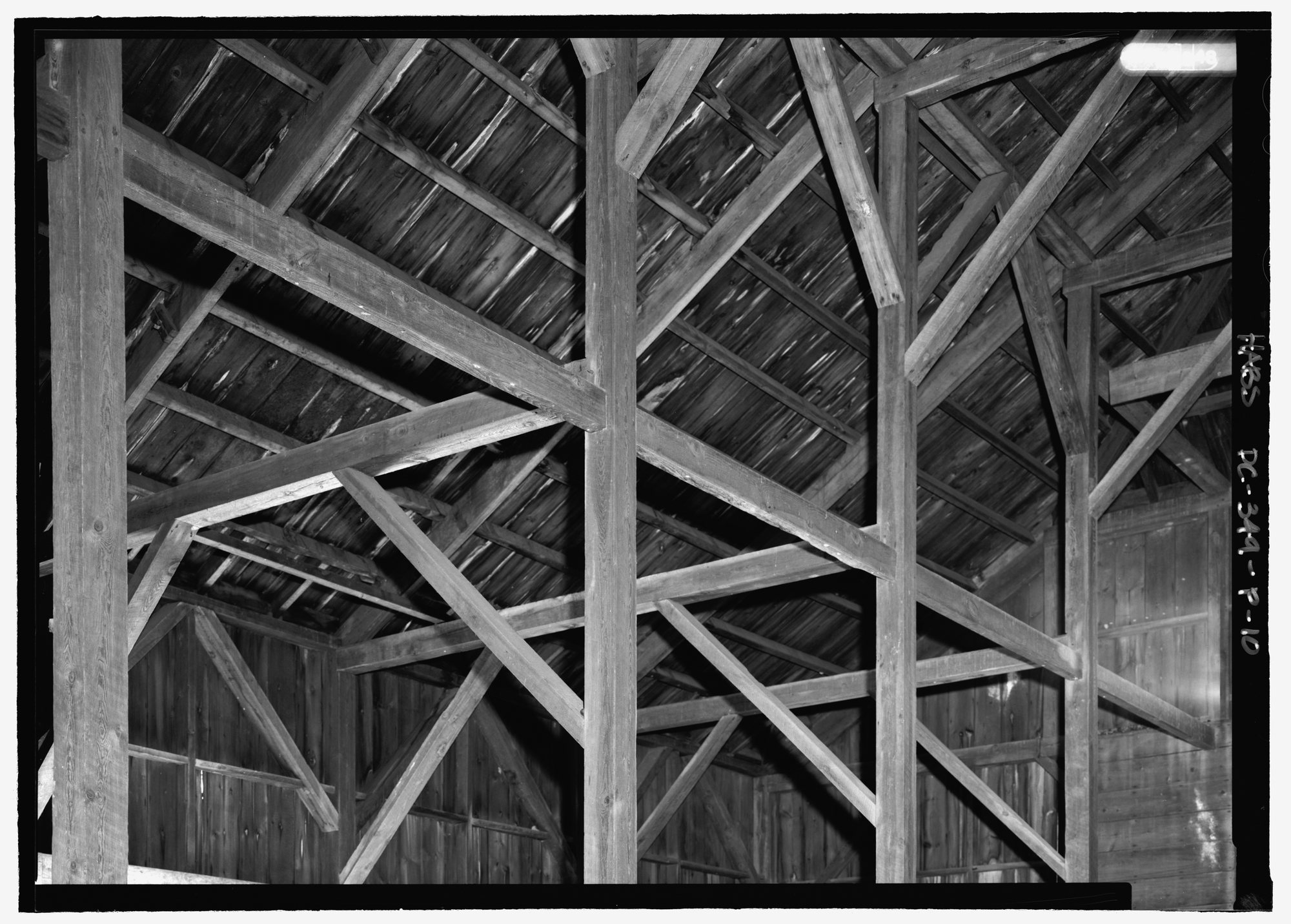
That barn was built in 1884 to accommodate a hospital dairy herd and associated work, later altered, and demolished in 2022. Its survey is thus also an archive of a structure that no longer stands. A clean frame graphic can make the building seem timeless and unoccupied; the hospital's agricultural operations, workers and animals were part of the architectural history. “Recorded in 2005” and “built in 1884” are different dates, and the photographed roof no longer survives in that building. [20]
Cutaway, stair and the ethics of what a drawing leaves out
Another HABS sheet records Building 22 at San Quentin State Prison. Pier Luigi Ferrari's 2009 drawing of Building B places an axonometric cutaway beside an entry-stair plan, stair section and photographs. One representation exposes the distribution of internal walls and levels; the others locate and inspect a specific threshold. This is an instructive format because the axo's three-dimensional clarity does not settle the staircase's actual dimensions, material or history of alteration. The sheet itself acknowledges that a building is better understood through several kinds of view. [21]
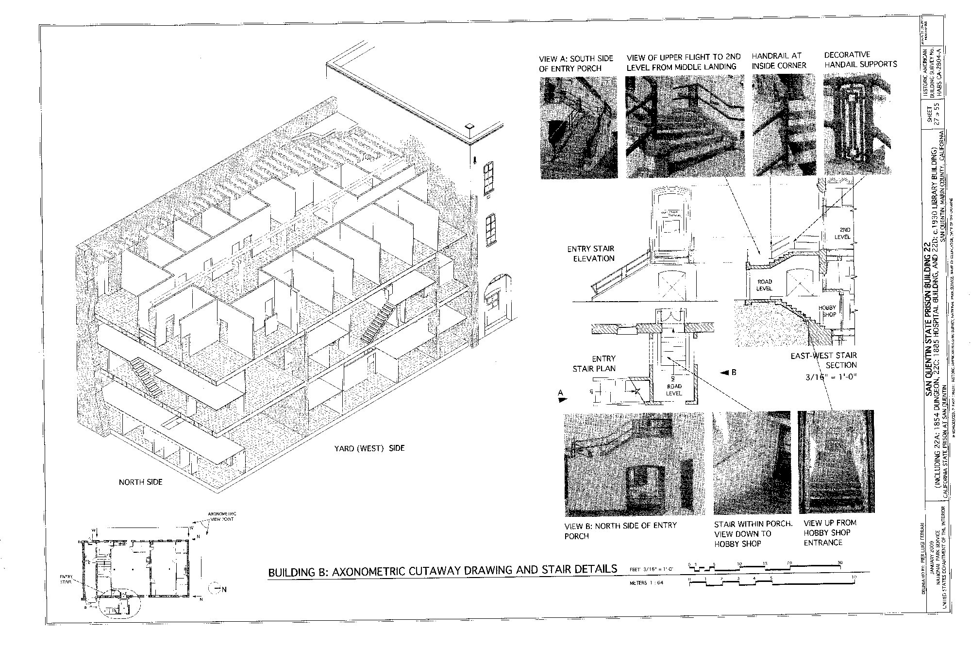
The context of a prison asks for even greater restraint. A cutaway may show cells, corridors and supervision-related geometry, but it does not tell us what incarceration felt like or who controlled access at different times. It cannot certify an accessible route just because stairs can be located, nor explain changing institutional policies from one measured sheet. The drawing is a spatial record of a specific building component. A responsible architectural reading combines it with the HABS history and other evidence rather than treating a legible diagram as a complete account of confinement. [21]

Text alternative for the diagram
An invented cutaway is accompanied by an abstract plan, section and photographic symbol; no HABS survey tracing.
Three spans, three trusses, and a bridge that is gone
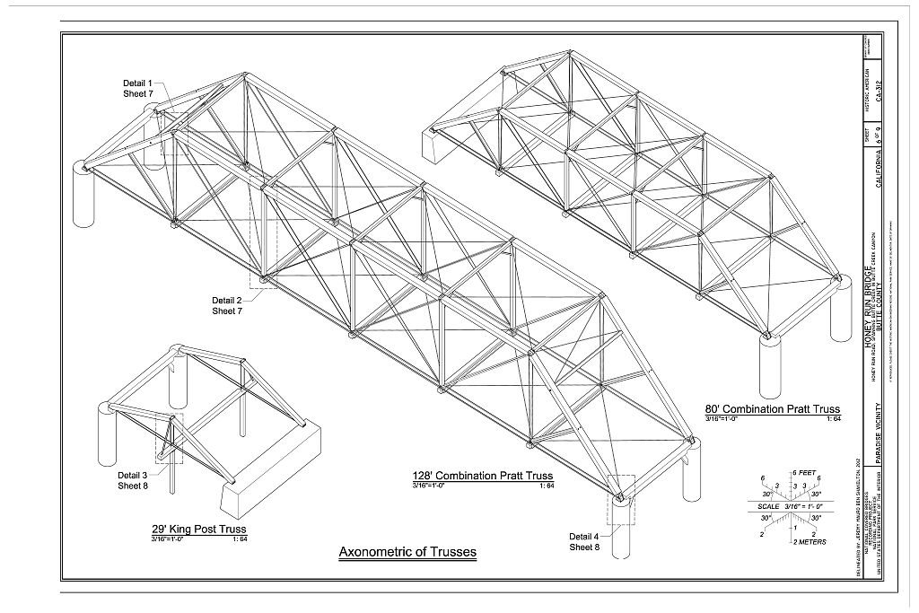
The Historic American Engineering Record's 2012 Honey Run Bridge sheet draws several truss configurations separately: an approximately 29-foot king-post arrangement and combination Pratt forms across longer 128- and 80-foot spans. Its axonometric lines direct the reader to other numbered sheets for connection details. From this one image, the engineering difference among spans becomes much easier to see than it would in a general riverbank photograph. Yet the callouts themselves warn that the joint geometry and member data are elsewhere in the set. The axo is a map of a structural system and of where further evidence lies. [22]
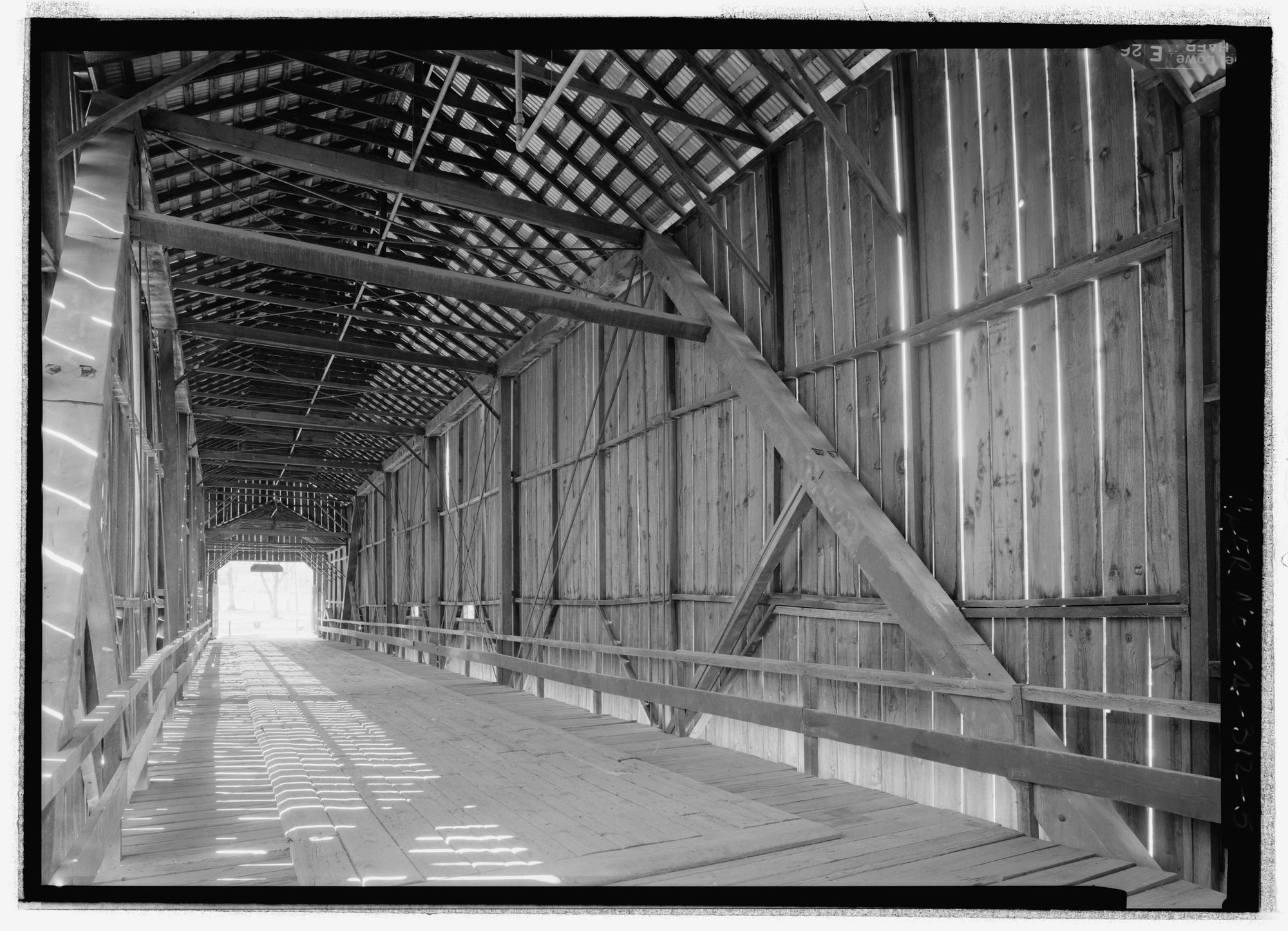
Jet Lowe's 2004 photograph of an interior span shows decking, light through the covered enclosure and the braced timber at a particular location. It helps ground the survey's skeletal trusses in a built environment, while the axonometric explains components that the single camera angle hides. The bridge dated from about 1886, was altered during the twentieth century and was demolished in 2018, as the Library of Congress record now states. The drawing and photograph document historical states. They must not be captioned as images of an extant original bridge or an unchanged 1886 construction. [22]

Text alternative for the diagram
A short triangular king-post scheme and two longer Pratt-like spans are new structural abstractions, not copied HAER geometry.
The bridge case also rebuts the idea that a visually neat axonometric is a complete engineering answer. Piers, abutments, fasteners, materials, loads and the construction chronology need more than a simplified three-dimensional depiction of trusses. In a historic survey, the advantage of the axo is to coordinate the long-spanning parts and make the reader able to follow the detailed sheets, not to certify the bridge's safety or permit its recreation from one image. [3], [22]
Exploded layers and drawings at different project phases
An exploded axonometric deliberately lifts layers or components apart. It can clarify which floor sits over a service zone, how a panel system meets a frame or which volumes form a competition proposition. The gap on paper is an explanatory interval, not a literal air space in the completed building. If the separated pieces represent a proposed construction sequence, the stated order of assembly may differ from their vertical order in the image. A cutaway does something different: it leaves the building notionally assembled but removes selected surfaces to expose what lies behind them. Both are conventions that can be misunderstood without identifying the parts and the drawing's purpose. [17], [26]
The CCA's record of an exploded Eisenman/Robertson drawing for a 1986 Parc de la Villette proposal makes the phase issue unavoidable: the sheet is an unbuilt competition proposition. It cannot be used as a description of the park's eventual fabric. An Italian student thesis catalogued by Politecnico di Milano likewise separates an exploded concept sheet from plans and construction details. In that unbuilt house-and-work project, the drawing classes answer different questions: an exploded image can show how parts relate, while a detail must state precisely how they meet. [17], [26]

Text alternative for the diagram
Four invented component plates are spaced vertically to reveal order and relations, not finished physical gaps.
An architectural sheet may also be redrawn after construction or published in a later exhibition. The Smithsons' 1956 House of the Future final-scheme axonometric, Choisy's 1899 historical church reconstruction, de Teresa's 1980 working museum drawing, Allen's 1984 later interpretive sheet and HABS's 2005 barn survey all use related visual devices but occupy separate places in a project's life. Treating them all as “the original design” would be false. The date and stated purpose of the object are therefore as important to interpretation as the direction of its axes. [6], [14], [18], [20]
The moving axonometric and the digital model
Eleanor Suess's University of the Arts London research adds movement to a form often imagined as perfectly static. In her acrylic-cube and cyanotype experiments, the orientation of transparent boxes, their shadows and the position of a screen produce images that can be read as plan-oblique, elevation-oblique or apparently inverted projections. In film, a fixed contact surface and moving light offer clues that a still image lacks. Her Axonometric Portrait 6 rearranges nine clear cubes over time, changing how a compact field of edges and shadows may be perceived. This is an artists' film and drawing experiment, not an instruction sheet for constructing a building. It reveals why a viewer's reading of “up,” “down,” “front” and “back” is not purely given by geometry. [24]
Stan Allen describes another change in the computer age. Digital modelling can output a parallel-looking view quickly, but architectural plan-oblique truth will not automatically follow from merely rotating a camera around a three-dimensional model. A model-derived orthographic axonometric has its own legitimate geometry, while a plan-oblique requires a different construction if its horizontal plan is to remain undistorted. Allen suggests shearing/rotating model geometry and then reworking a two-dimensional underlay, a choice that makes a specific graphic argument rather than pretending software produced a neutral view. His terminology reflects architectural practice, so the lesson is not that digital orthographic axonometry is “fake”; it is that the type of projection, alteration and emphasis must be known. [2], [16], [24]

Text alternative for the diagram
Three invented cube views distinguish fixed orthographic geometry, moving camera and light direction.
Tectónica's current publisher account similarly places constructive axonometrics beside three-dimensional models and BIM data. A richly rendered model can help locate hidden services or identify a window junction, but its polish cannot verify that site-built material agrees with what was modelled. Digital layers, graphic textures and cast shadows may make a diagram persuasive even when a necessary joint is unresolved. The test is whether the projected parts correspond to drawings, specifications, built photographs and the particular material problem being explained. [28]
Reading the sheet as evidence, not as total architecture
To read an axonometric well, first identify whether it preserves a plan, an elevation or none of the principal faces undistorted. Then locate the cuts. A white opening may be a removed wall, a finished window or an intentionally blank field; hatching can mean cut masonry rather than a surface finish. An exploded gap may represent assembly, analysis or merely a visual separation of systems. Without a legend or an object record, those conventions remain guesses. The most confident architectural interpretation is not always the most visually immediate one. [1], [2], [3], [4], [6], [14], [17], [18], [19], [20], [21], [22], [23], [24]
Next ask who made the drawing, when and for what task. An individual draughtsperson can have a distinct authorship within a collaborative office. Van Doesburg's hand on an archive sheet is not the sole authorship of Maison Particulière; Enrique de Teresa's working drawing and Stan Allen's later sheet are different contributions to Moneo's museum. A U.S. government survey sheet is not a Victorian architect's unaltered design. These distinctions change the kind of claim each image can support. [9], [10], [14], [15], [19], [20], [21], [22]
Finally restore what the projection removed. Choisy's bottom-up Tournus cut reveals arches and overhead enclosure but removes a plausible body and some context. Mérida's worm's-eye drawing intensifies the gallery ceiling while losing the street and archaeological ground that mattered to the design. The barn and bridge surveys can be read beside photographs of actual timber. The prison drawing needs institutional history and the voices of people, not only a controlled floor distribution. The axonometric's gift is precisely its selectivity; its danger is that an elegant selected relation can be mistaken for the whole building. [6], [7], [8], [14], [20], [21], [22], [23], [24]
An axonometric drawing is not a lesser perspective or an all-purpose proof. It is a powerful architectural argument: sometimes about a city, sometimes about a vault or connection, sometimes about how a building might be, and sometimes about the trace a lost structure leaves in a survey. The Russian city plan, Choisy's Tournus reconstruction, the Mérida office sheets and the HABS records make those different tasks—and their dates—visible without turning one projection into a universal account of architecture. [6], [14], [17], [18], [19], [20], [21], [22], [23]
Explore RELATED Artworks and Records
Four distinct sheets, each with its own source record and a different architectural purpose.

St Petersburg urban survey
Historic lifted city plan
de Saint-Hilaire, Sokolov and Gorikhvostov survey team
Choisy Tournus reconstruction
Constructive historical cut
Auguste ChoisyWhite House HABS survey
Dated measured-building view
Historic American Buildings SurveyHoney Run truss sheet
Engineering relation among spans
Jeremy T. Mauro for HAERWatch: Axonometric Portrait 6
Eleanor Suess’s moving-drawing experiment changes the reading of transparent cubes and their shadows; it is not a construction tutorial.
Transparent cubes, light and moving orientation
An original artist’s film helps explain why one still projection cannot convey every change in viewpoint or shadow.
Original illustrated preview, not a video still.Frequently Asked Questions
No. Strict isometric is one orthographic axonometric type. Architectural plan-oblique and elevation-oblique drawings are also often called axonometric, but preserve different faces. [1] [2] [24]
Only where the projection, scale and axis treatment are known. A ruler applied to an arbitrary diagonal in an unlabeled axo is unreliable. [1] [3]
His bottom-up cuts made supports, arches and overhead constructive relations visible together; they were analytical reconstructions, not ordinary floor-level views. [5] [6] [7]
They belong to Moneo’s museum project, but the 1980 working sheet was drawn by Enrique de Teresa and the May 1984 worm’s-eye sheet by Stan Allen in Moneo’s office. [14] [15]
Generally no. The White House, Cow Barn and San Quentin examples here are later dated federal measured-survey or analytical records, with drawing and photograph authors credited separately. [19] [20] [21]
References
- Brown University, Axonometric Projections.
- Columbia GSAPP, Introduction to Projection.
- University of Rochester, How to Create Effective Shop Drawings.
- CUNY Architecture OER, Architectural Drawings: Plans and Elevations.
- INHA, Auguste Choisy: critical biography.
- BnF Gallica, Auguste Choisy, Histoire de l’architecture, volume 2, 1899.
- Patricia Sabín-Díaz and Enrique M. Blanco-Lorenzo, La axonometría constructiva en arquitectura, UPC 2018 chapter.
- B. Kerekes and E. Korthals Altes, The Technics of Axonometry Through a Worm’s Eyes, TU Delft.
- Nieuwe Instituut, The Structuralist Architectural Drawing: Five Types.
- Nieuwe Instituut, Van Doesburg and Van Eesteren’s Maison Particulière.
- Nieuwe Instituut, Collectie Van Doesburg conservation account.
- MoMA, The Many Lives of El Lissitzky’s Proun 19D.
- Michio Kato, Japanese article abstract on Chernikhov’s architectural fantasies, J-STAGE 2001.
- Stan Allen, Drawing with Rafael Moneo, Madrid 1984.
- Rafael Moneo Arquitecto, National Museum of Roman Art project record.
- Stan Allen, John Hejduk’s Axonometric Degree Zero.
- CCA, Eisenman/Robertson Parc de la Villette exploded axonometric record.
- CCA, Alison and Peter Smithson House of the Future final axonometric record.
- Library of Congress, White House HABS ground-floor axonometric, 1992.
- Library of Congress, St Elizabeths Hospital Cow Barn HABS survey and framing sheet.
- Library of Congress, San Quentin Building 22 B HABS cutaway and stair sheet, 2009.
- Library of Congress, Honey Run Bridge HAER survey and truss axonometric.
- Wikimedia Commons, eighteenth-century St Petersburg Sennaya axonometric-plan source file.
- Eleanor Suess, Constructing the architectural moving drawing, UAL PhD.
- Leuven University Press, The Hybrid Practitioner, chapter 8 on architecture from drawing.
- Politecnico di Milano, 2014 house-and-work thesis record.
- Hochschule Campus Wien, Architecture—Green Building curriculum, Darstellende Geometrie 1.
- Tectónica, publisher account of constructive axonometrics.
- MIT Press, Edward R. Ford, The Details of Modern Architecture, volume 1.
Explore RELATED Architecture
These built-place pages show why plans, perspective, photographs and later records must be read together.
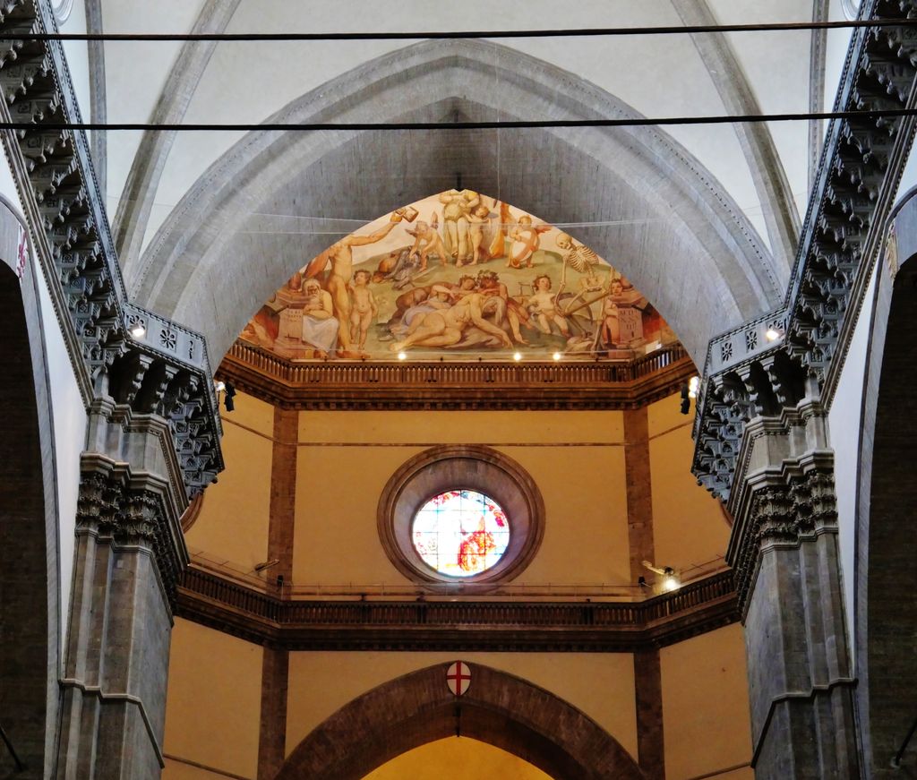
Florence Cathedral
Dome supports and layered construction invite sectional, not only surface, views.
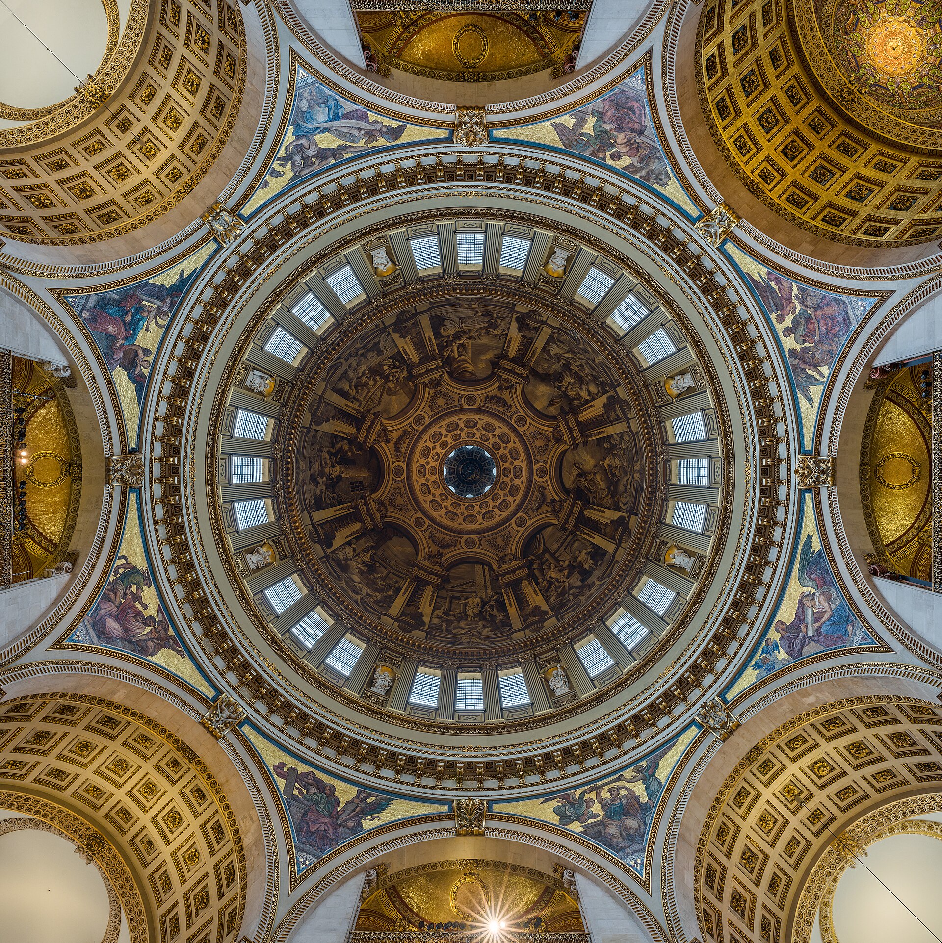
St Paul’s Cathedral
A bottom-up study can distinguish an overhead enclosure from its optical interior.
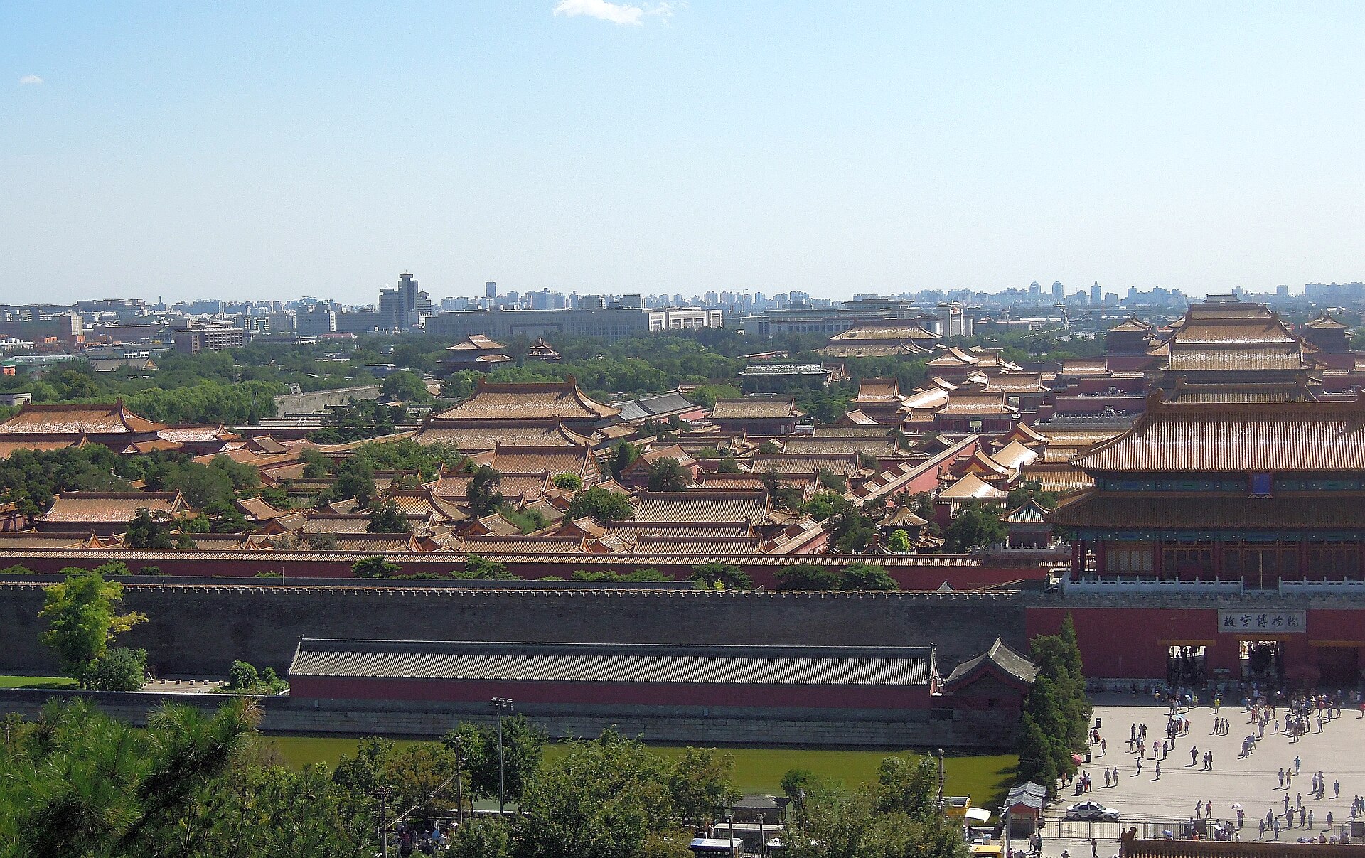
Forbidden City
Repeated courts and roofs suit parcel- and axis-scale lifted analysis.

Machu Picchu
Terraces, paths and height changes demand topographic companions to any axo.

Borobudur
Successive levels and routes are clearer when plan and elevation are read together.
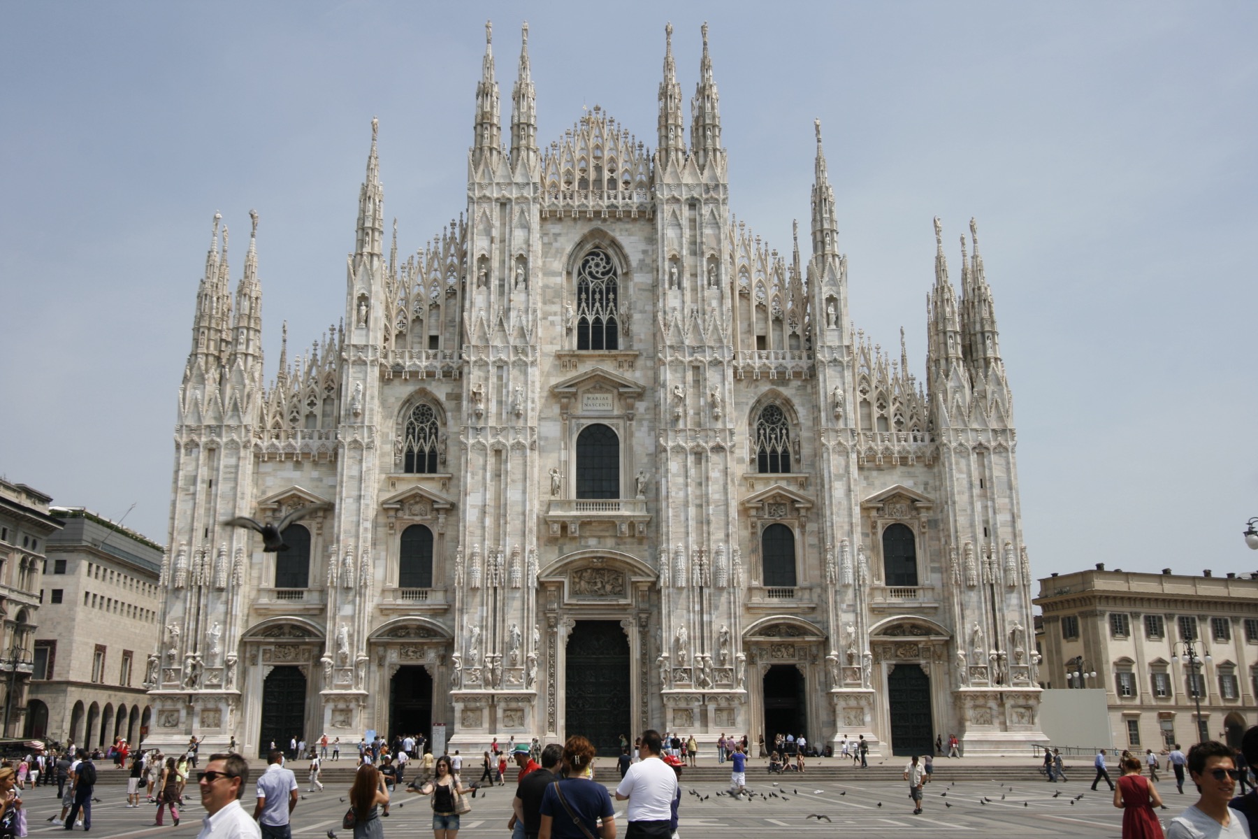
Milan Cathedral
A constructive cut can clarify structural bays a façade view leaves hidden.
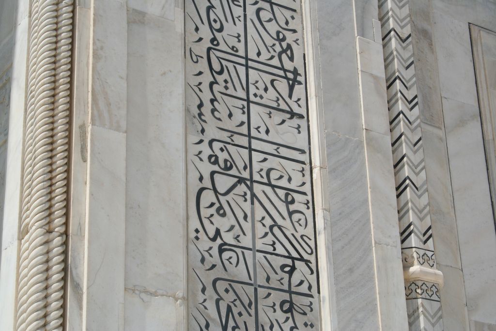
Taj Mahal
Garden axes and platform relations benefit from an undistorted-plan view.
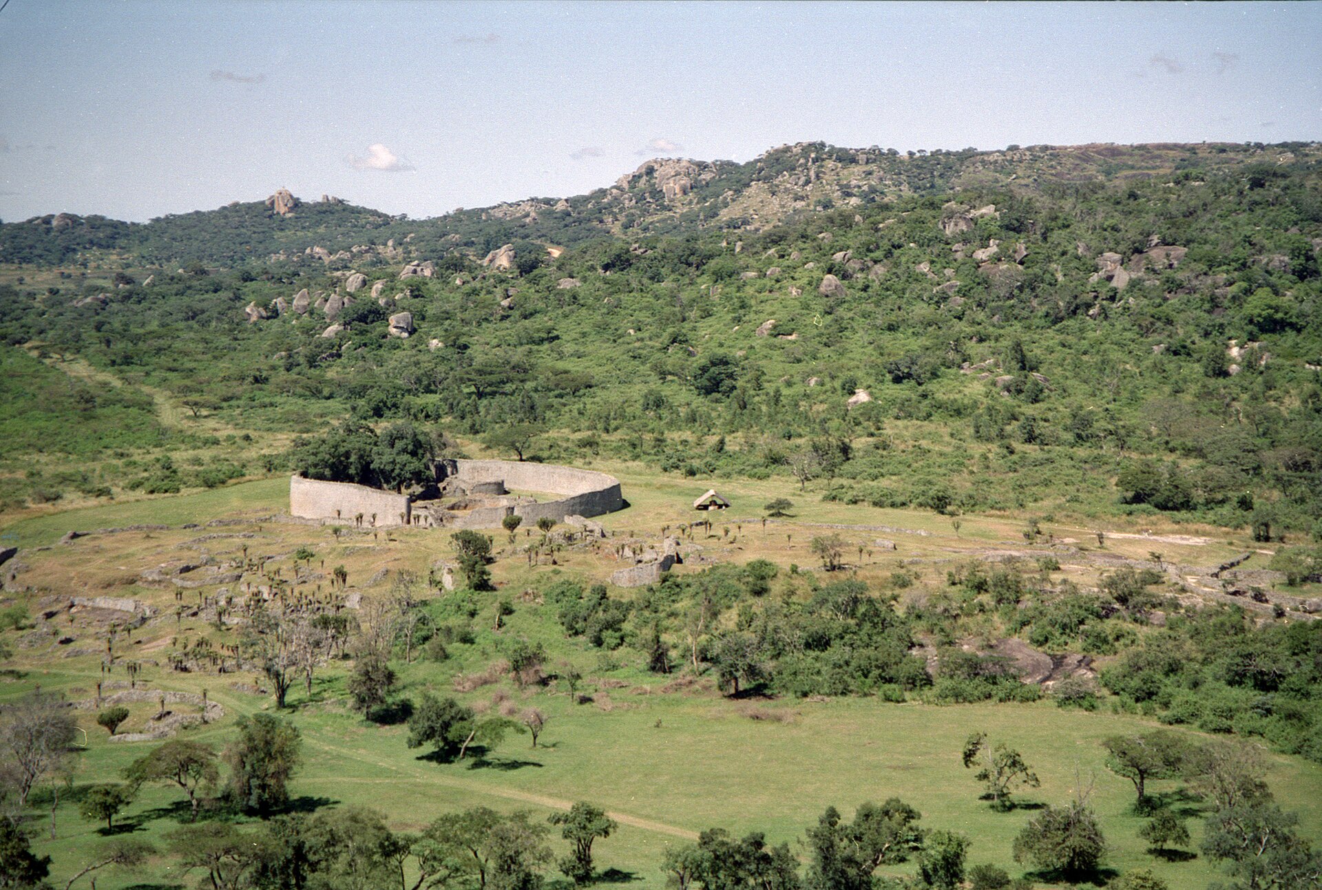
Great Zimbabwe
A lifted site drawing can show related enclosures without mistaking them for one building.