


 by Tom Gurney
Tom Gurney BSc (Hons) is an art history expert with over 20 years experience
Email: tomgurney1@gmail.com / Phone: +44 7429 011000
A composite made through position, connection and work
Reinforced concrete is not simply concrete with metal hidden inside it. It is a structural composite in which the arrangement of reinforcement, its anchorage and its interaction with surrounding concrete allow the materials to carry forces together. Concrete contributes useful compressive resistance; positioned reinforcement can carry tensile forces and influence cracking. The position and continuity of that metal matter as much as its presence. A handful of bars placed arbitrarily in a casting does not describe a functioning reinforced system. [1], [2], [3]
Its architectural history began with practical problems rather than a single modernist appearance. Boats and garden containers needed alternatives to decaying wood; floors needed economical construction and better protection against fire; engineers wanted dependable ways of crossing rivers, supporting factories and organising public buildings. Later frames, walls and shells changed the relationship between structure, rooms, daylight and façades. Those possibilities were realised through experiments, patents, contractors, calculations, supply networks and building work, not through the discovery of one universally applicable shape. [13], [14], [15], [16], [17], [18], [19], [20]
At a Glance
- Basic principleConcrete and embedded reinforcement act together through bond and anchorage. [1], [2], [3]
- Tension and compressionReinforcement contributes tensile resistance; concrete and metal have different, interacting structural roles. [1], [3]
- CrackingCracked behaviour is part of ordinary reinforced-concrete analysis, not proof that every crack is harmless. [2], [3]
- Hidden constructionBar position, cover, connections and the ability to place concrete affect the finished composite. [1], [3]
- Historical beginningsLambot, Monier, Wilkinson, Hyatt, Coignet and Hennebique addressed different objects, assemblies and commercial systems. [13], [14], [15], [16], [17], [18], [19], [20]
- Architectural possibilitiesFrames, load-bearing walls, flat or ribbed floors and shells organise space differently. [7], [8], [9], [10], [11], [12], [29]
- Material distinctionsReinforced masonry, ferrocement, fibres and prestressing are related but not interchangeable terms. [4], [5], [6], [30], [32]
- MakingIn-situ casting, factory precasting and hybrid assembly require different temporary support and connections. [7], [11], [12]
- PreservationCover, water, carbonation, chlorides and reinforcement corrosion are interdependent. [1], [32], [36]
- ReuseRetaining a frame or reusing a whole structural component differs from crushing concrete into aggregate. [34], [35], [37]
Contents
- How the composite carries forces
- Bond, anchorage and the concrete around a bar
- Reinforcement is made on site as well as on paper
- Similar names, different material systems
- Objects and floors before the continuous frame
- Hyatt's experiments: fire, bending and daylight
- François and Edmond Coignet are not one contribution
- Hennebique: a system and an organisation
- Institutions could change the architecture of a frame
- Factories, decorated offices and bridges
- Perret's rue Franklin: freedom within a particular household
- Dom-Ino: a proposal, not a photograph of a built system
- Japan: structural knowledge had several audiences
- Japanese caissons: making, transport and exposure
- Argentina: the system met local resources and contracts
- Shells: curved form still has a building history
- Frames, walls and floors organise different interiors
- Precast, in-situ and hybrid construction
- Prestressing changes the starting condition
- Cover, water and corrosion
- Repairs can concern the whole system
- Retaining a frame is not merely recycling its rubble
- Reusing structural pieces: realised arch, proposed housing
- Reinforced concrete does not dictate one society or style
How the composite carries forces
A useful first distinction is between compression, which tends to shorten a material, and tension, which tends to pull it apart. Concrete's usefulness in compression does not make an ordinary concrete beam equally effective in tension. Under bending, different parts of a member experience different demands. Reinforcement placed where tensile forces must be carried can make a concrete member behave very differently from an otherwise similar unreinforced casting. This explanation concerns the interaction of materials, not a rule that every bar is always in tension or every piece of concrete always in compression. [1], [3]
Reinforcement is therefore a geometry as well as a material. Longitudinal bars, transverse reinforcement and the smaller elements that hold an assembly in position do not all have the same purpose. A visible cage may contain members intended to contribute to bending or shear resistance alongside pieces needed to maintain its arrangement during casting. The completed outer surface conceals those distinctions. Two beams with the same outline can contain different systems and cannot be assumed to have identical behaviour. [1]
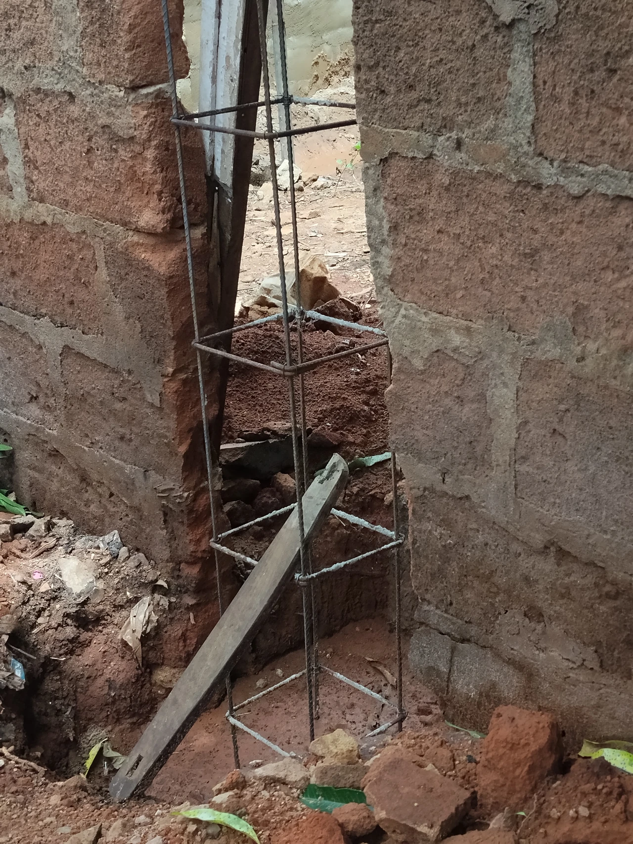
Cracking is central to understanding that behaviour. In a reinforced member, tensile cracking does not automatically mean that the composite has stopped carrying forces. Metal can continue to carry substantial tension across cracks while bond transfers force between the reinforcement and concrete. Concrete between cracks can still contribute to the member's response. The resulting effect, known as tension stiffening, helps explain why stiffness and deflection cannot always be understood by imagining that all concrete in tension vanishes from the calculation at the instant a crack forms. [2], [3]

Text alternative for the diagram
Original conceptual bond relationships, not measured stresses, a test specimen or proof that a visible crack is safe.
- A cracked composite still transfers force
- Conceptual — not measured
- Across a crack
- Positioned metal can carry tension across a concrete crack.
- Along a bar
- Bond transfers force; local slip and internal damage alter the interaction.
- Between cracks
- Concrete between cracks can contribute to stiffness through bond.
Nor does reinforcement promise an entirely uncracked surface. Its arrangement influences the distribution and development of cracking, but cracking can arise from loading, shrinkage, temperature changes, restraint, settlement or corrosion. These causes may overlap. Anticipated cracked behaviour in a structural model does not establish that a particular crack is safe. Width alone, especially in a photograph, cannot provide that verdict. [2]
The important architectural consequence is that structural action is not fully visible in the finished form. A thin slab, a large opening or a cantilever may invite an explanation, but their appearance does not reveal reinforcement, support conditions or construction quality. Drawings, investigation and the history of making can explain a building in ways its silhouette cannot. Reinforced concrete's apparent unity is achieved through an internal arrangement, rather than simply being a natural property of an artificial stone. [1], [2], [3]
Bond, anchorage and the concrete around a bar
Bond is the interaction that permits force to pass between reinforcement and concrete. Initial adhesion, friction associated with contact and roughness, and the bearing of bar ribs against surrounding concrete can contribute in different ways. Initial adhesion can be lost locally as slipping develops. These mechanisms do not make the interface an everlasting, perfectly rigid glue line. Local slip and cracking alter how force is distributed along a bar. The ribbed surface of much modern reinforcement is important because its geometry participates in mechanical interaction with the concrete. [3]
Michael Auer's German dissertation at the Karlsruhe Institute of Technology examines this interaction with particular attention to damage in concrete. Around a ribbed bar, force transfer can produce local bearing, internal cracking and changes in the surrounding material. Primary visible cracks are only part of that process. Secondary internal cracks and redistribution along the reinforcement help explain why a member's behaviour is more complicated than one smooth bar pulling uniformly against an intact solid block. [3]
Anchorage connects this local interaction to the wider structural arrangement. A bar must be able to develop the intended transfer of force rather than merely finish at the edge of a casting. Straight or hooked anchorage, overlapping bars, mechanical connections and appropriate welded arrangements are different ways of organising continuity. Their presence and detailing matter; they are not interchangeable decorative bends. In historic buildings, a patent name alone does not establish which connections were actually made. [1]
The surrounding concrete matters too. Rib-induced forces can damage local concrete or encourage splitting towards the outside of a member. Cover and confinement influence these different responses. Cover is consequently more than a protective skin applied after the structure exists: its position belongs to the geometry of the composite while also separating reinforcement from its exposure environment. The structural and durability histories meet in this apparently modest layer. [1], [3]

Text alternative for the diagram
Original anchorage and confinement symbols. Not required lengths, bar spacing, approved fabrication or a surveyed historic joint.
- Metal must connect to its surroundings
- Conceptual — not measured
- Embedded length
- Force transfer develops along an anchored bar, not at a magic end point.
- Overlapping bars
- An overlap needs surrounding concrete to transfer force between bars.
- Cover / confinement
- Concrete around bars and transverse metal affect splitting and interaction.
Testing also requires care in interpretation. Auer distinguishes pull-out, push-in and tension-tie specimens, which impose different conditions rather than yielding one universally transferable bond curve. In his damaged-interface model, the same amount of slip can accompany different transferred forces and distributions. The model was compared with specified experiments, while its outlook sought wider investigation of specimen geometry and calibration. Casting position can affect bond differently during service-level slipping and ultimate failure. These distinctions show why the largest reported test load cannot stand in for every aspect of a member's occupied life. [3]
Reinforcement is made on site as well as on paper
Before casting, reinforcement has to be fabricated, assembled and maintained in its intended position. Spacers and supporting pieces help preserve cover and geometry while concrete is placed. The cage must remain accessible enough for concrete to pass between members and fill the surrounding space. Congested reinforcement makes that task more demanding. An elegant calculation and a crowded, poorly filled assembly are not the same achievement. [1]
This is one reason to distinguish structural reinforcement from assembly work without dismissing the latter as incidental. Pieces that keep bars correctly positioned can be essential to obtaining the intended finished arrangement. Workers preparing reinforcement, making forms, placing material and coordinating sequences participate in the creation of the composite. The apparent simplicity of a finished column hides a series of operations whose quality cannot be recovered from its outline alone. [1], [25], [26]
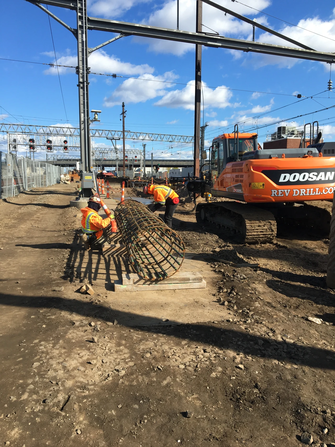
Temporary construction is equally important. Formwork holds the shape and helps support fresh concrete until it can support itself within the intended system. The permanent floor or wall is not responsible for every load during every stage of casting. Site forms, permanent insulating moulds, precast units and hybrid wall systems organise this transition differently. Reinforced concrete's capacity to take a shape does not eliminate the need to make and support that shape. [7], [11]

Text alternative for the diagram
Original making-stage symbols, not instructions for removing forms, temporary works or a claim that every frame uses this sequence.
- Temporary support is not the final system
- Conceptual — not measured
- Forms / supports
- Fresh concrete and reinforcement depend on temporary shape and support.
- During hardening
- Temporary work remains part of the construction sequence.
- Permanent structure
- The intended completed arrangement is distinct from casting-stage support.
Casting conditions leave an internal history as well as a surface one. Auer's discussion of bar position during casting connects local bond to how concrete develops around the reinforcement. Japanese port research likewise links congested bars, compaction and staged joints to construction difficulties in large reinforced boxes. These are not separate concerns added after structural invention; they are part of turning a proposed material arrangement into a workable object. [3], [26]
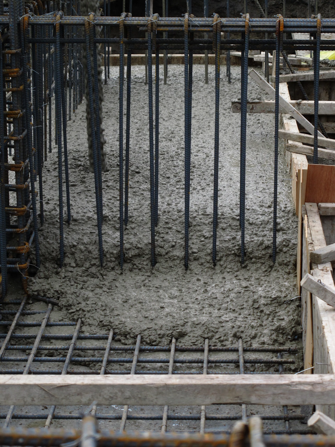
Similar names, different material systems
Historical words such as reinforced cement, ferro-concrete and ciment armé do not always describe a present-day specification. Some early patents combined metal with plaster or lime-based materials; others joined reinforced brickwork to concrete ribs. It is misleading to translate every such assembly into the same modern concrete frame. The matrix, reinforcement, construction sequence and way forces pass between parts all require attention. [14], [17]
| System | What is combined | Important distinction |
|---|---|---|
| Plain concrete | A hardened cementitious matrix with aggregate | Its presence does not establish an embedded reinforcement system. [7], [12] |
| Ordinary reinforced concrete | Concrete with positioned bars, mesh or other designed reinforcement | Bond, anchorage, placement and continuity make the materials act together. [1], [2], [3] |
| Reinforced masonry | Individual masonry units with reinforcement in joints or grouted cores | It remains a unit-masonry assembly rather than simply a poured concrete frame. [6] |
| Ferrocement | Hydraulic-cement mortar with distributed continuous fine metal mesh | Fine mesh and a mortar matrix distinguish it from an ordinary coarse-aggregate bar-reinforced member. [4] |
| Fibre-containing concrete | Concrete with dispersed metal, mineral or polymer fibres | Different fibres serve different purposes and do not automatically replace a designed bar cage. [5] |
| Prestressed concrete | Concrete deliberately compressed through tensioned reinforcement | An active initial force distinguishes it from ordinary passive reinforcement. [30], [32] |
| Precast concrete | Products formed before delivery or assembly, commonly under factory conditions | Manufacture alone does not specify whether an object is reinforced, prestressed or nonstructural. [12] |
Reinforced masonry is particularly easy to confuse with reinforced concrete because both can contain concrete-like infill and embedded steel. The Concrete Masonry and Hardscapes Association distinguishes unit masonry reinforced through mortar joints or grouted cores from grouting considered by itself. Filling cavities does not automatically establish reinforcement counted as part of structural resistance. Masonry bond may also mean the arrangement of units, rather than the physical interaction between metal and its surrounding material. The same word can refer to different questions. [6]
Ferrocement adds another distinction. The Food and Agriculture Organization describes a hydraulic-cement mortar reinforced with a distributed network of continuous fine mesh. Making that network and placing mortar through it involve labour, supervision and material availability. Historic claims of inexpensive construction depend on local labour economics; they should not be treated as evidence that the method is universally cheap, or that skilled planning and testing become unnecessary. [4]
Dispersed fibres form a further family rather than one universal improvement. Metal, mineral and polymer fibres differ in shape, dosage and intended role. Depending on the application, they may influence cohesion in fresh material, crack response, ductility, wear or behaviour in fire. These roles are not all supplied by every fibre, and a fibre-containing mix is not automatically equivalent to any bar-reinforced structural arrangement. Nineteenth-century experiments with particular fibres likewise cannot settle the capabilities of all later materials. [5], [13]
Objects and floors before the continuous frame
Joseph-Louis Lambot's boat experiments addressed a practical problem: wood decayed in damp conditions. The Provence Verte authority's museum history records an 1848 wire-reinforced cement boat prototype and the 1855 exposition and patent context of another boat. A metal trellis with hydraulic cement offered a way of making a vessel without relying on a conventional wooden hull. That object belongs to the composite's history, but it was not a complete building frame or a proof that every later reinforced structure descended from a single boat. [15]
Lambot's ambitions extended to other damp-use objects, including containers and building parts, rather than navigation alone. The boats also have a history as surviving artefacts: the authority records their reappearance in 1953 and the prototype's museum custody in Brignoles. Their later preservation gives a physical counterpart to patents and promotional histories without turning a nineteenth-century prototype into a demonstration of every later structural use. [15]
Joseph Monier's work began with another everyday problem. As a gardener, he developed wire-supported cement containers as alternatives to wooden objects with limited durability. His 1867 patent was followed by extensions into further applications and by the 1875 Chazelet bridge. Foreign licensing and subsequent German development expanded the story beyond the original French filing. The progression from container to other components matters more than an unsupported claim that one patent instantly contained the entire later structural system. [16]
Monier's circumstances also challenge a simple story of invention rewarded. Patents, recognition and international use did not assure him lasting financial security. The professional heritage account records bankruptcy and difficult later circumstances. Technical diffusion, commercial ownership and the livelihood of an inventor were not necessarily the same success. The people whose names became labels for systems did not all control the eventual benefits of their work. [16]
In Britain, William Boutland Wilkinson's 1854 patent concerned fireproof floors, ceilings, roofs and stairs. Patricia Cusack's Edinburgh dissertation describes both cement-concrete arches with metal strips and flat floors reinforced with wire rope in materially different mixtures involving plaster or lime. These were not all one modern Portland-concrete recipe. Such floor-and-stair arrangements did not amount to an entire freestanding column-and-external-wall frame: their history is a contribution to reinforced construction, not the invention of every later reinforced building. [14]
Wilkinson's use of available wire rope connects design to supply. Looped or splayed ends addressed anchorage, while the drawn reinforcement did not occupy one completely standardised position in every variant. Similar-looking twisted metal in later systems need not have been chosen for the same reason. An economical available rope and a purpose-made deformed bar can both interact with surrounding material without sharing one historical intention. [14]
Henry Young Darracott Scott's 1867 floor proposals also combined iron ties, hoops or wire with a compression-resisting matrix. Some variants exposed cambered ties instead of embedding every component within concrete. A tie carrying tension is not, merely for that reason, evidence of deliberate prestressing. These experiments sit near reinforced concrete's development while preserving differences between a tied assembly and a fully embedded composite. [14]
Other patents addressed narrower parts of the problem. Cusack describes Peter Stuart's 1881 granolithic-floor proposal, in which a grid between concrete and surfacing supplied additional strength. Ernest L. Ransome's 1884 twisted square iron reinforcement sought continuous bond. The latter's deformation was a deliberate interface strategy, not simply the reuse of rope because it was available. Such examples reveal experimentation with surfaces, layers and anchorage rather than a straight sequence of complete, universally successful systems. [14]
Paul Cottancin's construction makes the terminology still more important. His wire networks and concrete ribs could coexist with reinforced or perforated brickwork and different column arrangements. It is therefore inaccurate to picture every Cottancin building as an identical solid concrete skeleton. These competing combinations were part of the environment in which later proprietary systems developed, not irrelevant mistakes erased by one eventual winner. [14], [17]
Hyatt's experiments: fire, bending and daylight
Thaddeus Hyatt's 1877 account gives unusually direct access to the questions asked of iron and concrete. Its stated concerns included economy of metal and security against fire in roofs, floors and walking surfaces. Hyatt distinguished an incombustible metal from a whole assembly capable of resisting fire: iron did not burn like timber, but exposed parts could still behave differently from metal enclosed by a protective material. He criticised arrangements that left iron flanges exposed while placing brick or concrete between them. [13]
His bending experiments compared different metal arrangements within specimens. Heavy upper metal could be wasteful, he argued, where concrete already contributed compressive resistance; lower ties offered another route to economy. David Kirkaldy's composite-beam tests belonged to the 1876–77 investigations. A table signed on 26 February 1877 distinguishes specimens, reinforcement and spans, rather than presenting one number applicable to every floor. Hyatt himself described one comparison as approximate and distinguished a possible arrangement from a recommendation. [13]
Fire testing investigated the assembly under more than one condition. Hyatt reported furnace trials, observations of heat penetration through different cover and loaded floor sections exposed to fire and subsequently water. Temperature indicators and measurements formed part of the apparatus. His publication's thermal graph helped present protection as an experimental question. He also argued from specimens that iron and concrete expanded similarly with heat; this was not a demonstrated law for every mixture and temperature. These reported tests explain why encasing metal was attractive, without supplying modern standard certification or a guaranteed fire-resistance period for an unrelated historic building. [13]
Hyatt's own revisions are revealing. Early bolts connecting lower ties to compressive members were later described as a misapprehension, apart from their use against horizontal slipping. It would be wrong to look at every vertical component in an early drawing and assign it the later role of a modern shear stirrup. The experiments were developing an understanding of interaction; they did not begin with every subsequent explanation already complete. [13], [14]
Daylight was another architectural application. Concrete-and-iron grids could hold glass inserts in walking surfaces, bringing light to basements below. Hyatt identified his Farringdon Road Lens Light Works and discussed roofs, floors and further possible applications. A grid could therefore address illumination and movement as well as load. His proposed church, dome and other uses must remain distinct from the particular works he described, but the connection demonstrates that early reinforced construction was not exclusively a story of opaque beams. [13]
The account also reveals collaboration and commercial ambition. Hyatt credited Birmingham engineer Thomas Rickett for solving experimental problems and preparing the publication, and anticipated further construction collaboration. Arguments about lighter metal handling and labour accompanied promotion of a proposed cement enterprise. Cusack traces reception despite the book's private circulation, including Cates's 1878 conference discussion and later professional references; subsequent patents extended beyond the 1877 tests. Laboratory work, publication and commercial development were connected stages, not a solitary moment of invention. [13], [14]
François and Edmond Coignet are not one contribution
The Coignet name can conceal materially different work. François Coignet's agglomerated or pressed concrete was concerned with manufacture and use of concrete itself. His son Edmond's reinforced-cement and engineering activity belongs to another stage. Calling every Coignet object reinforced concrete obscures this distinction, just as it obscures the boundary between a material-making process and an embedded structural arrangement. [17], [18]
The French engineering dossier records Edmond's 1882 reinforced-cement patent and his 1894 calculation presentation with Napoléon de Tédesco. Cusack also discusses an earlier 1889 presentation of tension-and-compression principles. These are different stages in relating practical construction to analysis, not contradictory dates that must be forced into one universal first-theory claim. Edmond's bureau, company and participation in the 1900 concrete commission further show how contractors and engineering institutions helped establish a field. [14], [17]
The Coignet company also continued under different teams. Later Coignet SA fabrication and engineering involved Gilbert Lacombe and Pierre Faessel, not personal designs by founders who had died decades earlier. A company name can survive changes in personnel and technique. It is useful evidence of industrial continuity, but it is not a substitute for identifying who developed or built a particular later system. [17]
Hennebique: a system and an organisation
François Hennebique came from the building trades rather than formal engineering training. Early work on fire protection and iron-and-cement construction preceded the broad system associated with his name. The professional heritage account distinguishes earlier trough-floor arrangements from later longitudinal reinforcement and transverse stirrups or straps. The 1892 patent and subsequent refinements, including 1897 additions associated with continuity across supports, were stages in an evolving construction system rather than an immutable object repeated unchanged worldwide. [19], [20]
His achievement also depended on organisation. Central calculations and drawings were combined with agents and concessionary builders who secured and executed work locally. The consulting bureau, patent filings and withdrawal from direct contracting did not all occur at one universally agreed founding date. The important sequence is the development of a commercial engineering network able to turn local commissions into calculated and detailed projects. A patent without that network would describe a different scale of influence. [19], [20]
Technical communication made the system visible. Annual congresses began in 1897, and Le béton armé started publication in June 1898. Articles and images carried explanations of construction while promoting the enterprise. Sandbag load-test photographs presented performance to potential clients. They can illuminate the way confidence was produced, but a publicity image is not equivalent to an independent modern certificate or evidence of every hidden detail in the photographed work. [19], [20], [21]
The network grew across modest projects and large programmes: housing, agriculture, industrial buildings, foundations, bridges and public works. Saint-Ouen's refinery and the Fives-Lille spinning mill attracted press attention. Different programmes required different geometries, spans, loads and execution, even when they shared a commercial system name. Their importance lies in broadening applications, rather than making every building a copy of one celebrated factory. [19]
Scale needs a date and a unit. The Cité account describes around thirty agencies and 160 concessionaires near 1900; the AFGC account gives 127 agents and 491 concessionaires in 38 countries for 1914. These are different snapshots, not inconsistent simultaneous totals. Tens of thousands of studied projects and the much larger archive of dossiers are not counts of buildings personally erected by Hennebique. They include the paper work of a network, which could include proposals never executed. [19], [20]
Competition remained important. Edmond Coignet and Cottancin offered other systems; local contractors and foreign practices developed alternatives. A German central office opened in Frankfurt in October 1898, although Berlin was also a significant setting for proposals. Archive studies cannot establish that every proposed Berlin project became a building. Expansion through agencies was negotiated within existing markets, not a frictionless replacement of all other construction. [17], [21]
Nor did patents secure permanent dominance. AFGC records the main patent's invalidation in 1903, while the larger organisation continued. War interrupted expansion, later business contracted and the bureau eventually dissolved in 1967. The material's diffusion outlasted the enterprise and cannot be reduced to one uninterrupted corporate success. The history joins legal protection, technical practice and contracting without treating any one of them as the whole explanation. [19], [20]
Institutions could change the architecture of a frame
A frame can separate structural support from an exterior wall, but historic regulations did not always recognise that distinction. Cusack's British study shows how rules specifying thicknesses appropriate to load-bearing masonry could obstruct economical thin panels without expressly banning reinforced concrete. A material might be usable inside a building while the façade still had to answer assumptions developed for a different structural system. Technical possibility and authorised architectural form were therefore not identical. [14]
Hybrid construction was one outcome. Reinforced floors within load-bearing brick or stone exteriors could be treated differently from a complete skeleton with thin infill. Provisions governing fire resistance, wall thickness and the proportion of solids to openings influenced what a warehouse or other framed building could look like. These restrictions concerned relationships between systems and authorities, not simply a dispute over whether concrete existed as a useful substance. [14]
The British situation was not uniform. Permissions and exemptions varied between local authorities, rural districts and particular government or transport-company properties. Some areas offered discretion that others did not. It is consequently misleading either to present one national ban as the entire obstacle or to assume that an exemption somewhere made every project elsewhere straightforward. The geography of administration was part of the geography of adoption. [14]
Financial arrangements added another layer. Cusack records survey-fee surcharges and shorter public loan-repayment periods for concrete construction compared with established masonry categories. These conditions could discourage municipal clients even where engineers believed a structure workable. Adoption depended on borrowing, inspection, precedent and confidence as well as drawings. This is a historical account of early twentieth-century conditions, not a statement of present building requirements. [14]
Factories, decorated offices and bridges
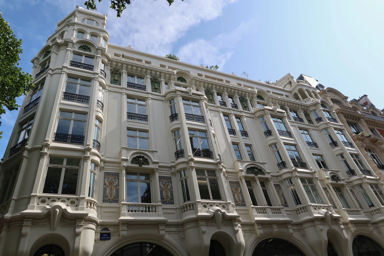
Rue Danton's engineering premises show that a reinforced frame did not demand the rejection of ornament. The 1900 building combined Édouard Arnaud's architecture with Hennebique's bureau and Alexandre Bigot ceramics. Art Nouveau decoration could accompany a system promoted as technically modern. The façade communicated both architectural identity and the enterprise behind the structure; ornament and engineering were not opposing categories. [17], [20]
An industrial mill at Nantes answered another set of demands. The engineering dossier credits architects Lenoir, Etève and Raoulx together with the concessionary firm E. and P. Sée. Grain storage, movement and processing helped organise the programme. Later known as CAP44, the building received metal cladding and an office conversion in 1974. Its changed skin and use demonstrate how a concrete structure's architectural life can continue through alterations that make its original appearance less immediately legible. [17]
Hennebique's Bourg-la-Reine house was a demonstration in a domestic and garden setting. Terraces, cantilevers and a water-reservoir tower displayed possibilities that were not confined to industrial floors. Elsewhere, grain silos, water towers, sports buildings and pools extended applications into storage, water and public activity. The system could serve expressive domestic promotion or practical infrastructure without making those programmes structurally identical. [17]
Bridges connected engineering arrangements to particular landscapes. At Camille-de-Hogues, constructed in 1899–1900, Maurice Dumas's proposal to use reinforced concrete instead of metal required technical acceptance as well as a design. Low arches and the deck arrangement answered the crossing's geometry. Its place in road-bridge history does not erase Monier's earlier Chazelet bridge: the dates and categories need to remain distinct, rather than being collapsed into an unqualified first bridge. [16], [17], [20]
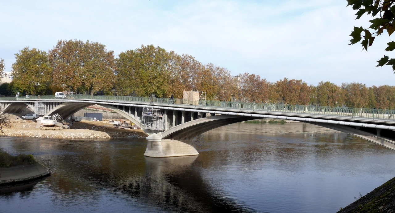
Executing firms were part of the work. The French dossier credits SA Fondations at Mativa, Paul Arnaud and Davat/Armand at La Mescla, and Giovanni Antonio Porcheddu at Risorgimento. La Mescla's above-deck arches responded to high water and a constrained valley. Such choices connect structural position to the river landscape, while construction and opening for service remain different events. A system name should not remove the contractors whose work made the crossing possible. [17]
The international network also operated in Algeria, Tunisia, Egypt and Italy through specific agencies and commissions. In North Africa and Egypt, this commercial expansion belonged to colonial contexts rather than a neutral transfer between abstract national styles. Named agents, architects and concessionaires explain some of the organisation, but they do not account for every worker who cast or assembled a structure. The absence of those names should not turn collective building work into personal authorship by a distant bureau. [17], [20]
Perret's rue Franklin: freedom within a particular household
The rue Franklin apartment building, designed in 1903–05, shows how structural and architectural questions meet on a constrained site. The Cité account records a plot only 15.87 by 13.13 metres, with one principal orientation and no opportunity for an ordinary rear courtyard. A frame offered an alternative way of arranging rooms and openings. A recess towards the street, bow-window possibilities and rear glass bricks addressed light within that specific urban situation. These are plot measurements, not the usable area of every apartment. [22], [23]
The Perret practice brought architectural education together with a family building enterprise, but it did not yet possess every reinforced-concrete capability itself. Latron et Vincent executed the frame. Design and contracting expertise were distributed, rather than residing in one complete master-builder from the outset. The brothers' design and construction roles also mattered to the practice that later identified itself with architects and builders in reinforced concrete. [22], [23]
The façade is not bare concrete. Smooth ceramic cladding articulates the structural members, while Bigot's flamed stoneware floral panels distinguish infill. The frame was made legible through another material. Perret later associated the cladding with concern about preserving embedded metal, but the result also gave the building an ornamental architectural presence. Structural expression could therefore be mediated by ceramics rather than achieved by exposing every cast face. [22], [23]
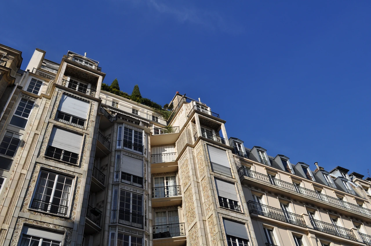
Inside, larger openings and non-bearing partitions created possibilities without completely overturning domestic convention. Enfilade living rooms and separate servants' circulation retained household hierarchy. A freer structural plan did not automatically become a socially free plan. Lift access and terraced upper levels also altered the desirability of apartments higher in the building. Structure, movement, status and urban regulation worked together, rather than technology supplying a finished social programme. [23]
The museum's apartment models make that distinction visible. Comparing Franklin with a nineteenth-century Haussmannian arrangement and a later 1925–28 type separates changing façade and plan conventions. A frame can permit a different partition arrangement while occupants and architects retain older forms of room sequence. The significant question is what was changed on this site and what continued, not whether one material mechanically abolished the nineteenth century. [23]
Perret's wider work further separates material from a single style. Classical rhythm, proportion and symmetry could organise a reinforced skeleton. The later, demolished Ponthieu garage offered a different glazed programme; the Champs-Elysées theatre combined construction with Bourdelle and Denis's artistic contributions. Raincy's church and the Palais d'Iéna's hall, helical stair and hemicycle answered still other uses. Offices, scientific buildings and exhibition structures extend that variety. Saint-Joseph at Le Havre, developed in 1949–57 and completed after Perret's death, also shows how a named architect's work could continue through subsequent teams and stages. [17], [23]
Professional transmission formed another part of the story. Le Corbusier's period in the Perret agency in 1908–09 came after Franklin, rather than making him its designer. It placed a future advocate of a different architectural programme near a practice that joined design and building. The significance of reinforced concrete here lies in what different architects made of its possibilities, not in a single universally agreed destination for modern architecture. [23], [24]
Dom-Ino: a proposal, not a photograph of a built system
Le Corbusier's Dom-Ino scheme dates to 1914 and arose in the context of wartime destruction and reconstruction. The Fondation Le Corbusier presents its retrospective explanation from the Oeuvre complète: standard frames could be combined while leaving internal distribution and façade lighting relatively independent. Floors and stairs became part of a structural kit rather than being inseparable from the final room plan. The familiar drawing represents a proposal, not proof that a whole settlement of these houses was immediately realised. [24]
The programme included more than a frame. A companion enterprise would supply standard windows, doors and storage partitions. Equipment was to be coordinated with construction, and material from damaged buildings could provide non-bearing infill. The proposed freedom of planning therefore existed alongside standardised products and a particular reconstruction economy. A minimal skeleton was not a complete dwelling waiting only for an arbitrary façade. [24]
Its making also requires a qualified reading. The retrospective account's description of construction without formwork is followed by special temporary steel beams, collars and column casting. These devices did not amount to the disappearance of all temporary support or moulding. The proposal reorganised construction apparatus and sequence; it should not be repeated as a literal promise that concrete floors could simply be made without the means to hold their geometry. [24]
Claims that owners could assemble houses without specialists belonged to the authors' social and commercial ambition. References to Flemish building precedents and Sicilian reconstruction broadened that ambition beyond one abstract diagram. They do not establish safe self-building instructions. The same retrospective account placed fuller application in the later Loucheur context, fifteen years after the initial scheme. Proposal, persuasion and later development are different stages. [24]
Franklin and Dom-Ino thus ask related but different questions. One is a realised apartment building negotiating a particular plot, façade and household; the other separates structure and equipment in a reconstruction programme. Reinforced concrete offered possibilities to both, but a proposed kit and a completed urban dwelling cannot be treated as interchangeable evidence. Their differences are precisely what makes the comparison architecturally useful. [22], [23], [24]
Japan: structural knowledge had several audiences
Shu Jianshuo and Takahiro Taji's Kyoto University study examines Japanese reinforced-concrete knowledge between 1906 and 1923 through textbooks and journals. Their argument distinguishes the development of bar arrangements and construction practice from the analytical models used to explain members. New structural forms did not automatically mean that every contemporary account treated the frame as one fully rigid, continuous system. Knowledge developed through several audiences and publications at different speeds. [25]
Terminology can conceal that difference. The historical term chōheki in the literature studied describes a frame with filled walls, not automatically the lightweight hung façade now commonly called a curtain wall. A shared English translation can make different building arrangements seem identical. Recognising the historical meaning prevents a modern façade product from being projected onto an early frame merely because both divide structure from some exterior enclosure. [25]
Hennebique and Kahn arrangements also coexisted with mixed stirrup, bent-bar and other solutions. They were not two permanently fixed systems transplanted without change. The study discusses competing explanations for Kahn-related difficulties: inherent arrangement and incomplete local construction technology were not treated as the same cause by every commentator. This history cannot justify a blanket verdict that all structures carrying one system name were intrinsically defective. [25]
Teaching often converged around elastic flexural calculations and neutral-axis assumptions. More advanced approaches were known, but simpler beam models continued to circulate, while complete rigid-joint or indeterminate-frame treatment remained limited in the examined material. An outwardly continuous frame could consequently be described through calculations that did not represent every aspect of its continuity. Architectural form and the history of analysis need to be read together without assuming that one photograph supplies both. [25]
Practical publications addressed another part of the task. Hibi's Osaka Asahi work and Kasamatsu's Mitsubishi Estate serials discussed formwork, preparation and placement of bars, casting and spacers. Such topics brought knowledge close to the operations of construction. Popular magazines, institutional journals, catalogues of foreign books and question-and-answer exchanges supplied different routes for information. Reinforced concrete spread through working instruction and discussion as well as formal theoretical texts. [25]
Supply complicated the transfer. Local concrete knowledge progressed while reinforcement remained substantially dependent on imported metal. The 1917 debate about cracking and terminology drawn from timber construction reveal how contemporaries interpreted unfamiliar behaviour, not present proof that cracks were harmless or joints literally acted like carpentry. Keiji Goto's analysis and Mikishi Abe's overseas experimental knowledge add further contributors to a history that cannot be assigned to one national hero. [25]
Japanese caissons: making, transport and exposure
Port structures show why a material label must follow the actual construction. Yamashita Ikuhiko and Fukute Tsutomu's Japanese study distinguishes lime or mass-concrete blocks, pneumatic caissons and later reinforced-concrete boxes. An earlier object called a caisson is not necessarily evidence of an earlier reinforced-concrete shell. The box, its compartments and its filling can perform different functions within an apparently massive harbour structure. [26]
The study dates reinforced-concrete caissons at Kobe to 1910 and relates their adoption to overseas observation and adaptation of making and transport. Casting a box shell, handling or floating it, sinking it into position and filling compartments are distinct operations. Concrete used as ballast or mass filling is not automatically the same structural material arrangement as the reinforced shell enclosing it. Marine work turns the distinction between component and fill into a particularly clear architectural lesson. [26]
Later large caissons increased the importance of staged casting, joints, congested reinforcement and compaction. Transport arrangements were part of design rather than a logistical detail added after the object was complete. Marine exposure further connected construction with durability. These findings belong to the study's 1992 historical perspective; they do not by themselves establish the present condition or later disaster performance of every structure it discusses. [26]
Long-term experiments are likewise time-bound. Hiroi's Otaru specimen programme began in 1896 and compared storage environments, making exposure part of the question being tested. The 1992 paper's projected centenary test and century-long service aspirations were still future statements. Their value here is to show a commitment to observing material over time, not to convert an intended later test into an outcome the paper could not yet report. [26]
Argentina: the system met local resources and contracts
Juan Pablo Pekarek's Spanish-language study locates Hennebique's Argentine activity within public-works reform in 1911–15. Officials questioned contractor accounting and design methods that could be detached from local resources. Reinforced concrete entered a debate about how the state should commission and construct buildings, rather than merely introducing a new aesthetic. Beaux-Arts training, materials, budgets and technical responsibility were intertwined. [27]
Buenos Aires's Post Office illustrates the hybrid character of the work. Concrete piles, an American steel skeleton and reinforced-concrete floors belonged to one project without making it a complete Hennebique concrete frame. Wartime interruption of imported metal encouraged debate about domestic materials and industry; local recovery of iron did not remove international dependence. Substituting a material required consideration of supply, not only a claim that national construction could become self-sufficient. [27]
Commercial networks helped connect the Paris bureau with these opportunities. Pekarek identifies at least 58 Argentine folders in the Hennebique archive, including unrealised studies. Agent Forgues worked through commercial, banking, engineering-school and governmental connections. The bureau could supply calculations and details for fees while concessionaires assumed local construction and financial responsibilities. Competing firms offered different packages, including integrated materials and turnkey execution. A technically attractive system did not necessarily provide the most convenient contract. [27]
Control of the name created friction. Local engineers wanted Hennebique's reputation to strengthen bids, while head office worried about errors in subcontracted execution and refused wider uses. Engineers complained about freight, labour demands and generic calculations that could be poorly matched to local resources. These were disputes over the practical organisation of knowledge and risk. They complicate the assumption that central calculation automatically made construction cheaper or more adaptable wherever the drawings travelled. [27]
One proposed reinforced-concrete postal dome was studied but not realised; a later German contractor supplied a metal structure. The paper history therefore cannot be read from a photograph of the eventual building as if the original concrete proposal had been executed. Conversely, the Caja Nacional de Conversión project was a realised intervention beneath an existing building: a vault and reconstructed ground-floor slab retained masonry supports and incorporated special security equipment from Fichet. These were different outcomes, one proposed and one hybrid and built. [27]
The vault exposed the distance between drawings and available components. Extended correspondence, disputed details and the absence of the specified twelve-metre bars contributed to delays and waste. Permission to use shorter joined pieces came after ordering had already created problems. The historical solution is not a present construction prescription; the episode shows how dimensions assumed in a remote office could conflict with local supply and timing. [27]
War delayed completion, and the eventual work did not lead to further documented state commissions after 1920 in the archive examined by Pekarek. That is a bounded archival outcome, not proof that no reinforced work occurred anywhere in Argentina. His broader argument is that architectural freedom and economy depended on whether a system was adapted to a pre-existing design or the design changed to exploit the system. Concrete did not erase negotiation over form, resources and institutional power. [27]
Shells: curved form still has a building history
Pier Luigi Nervi's sports architecture joined structural invention to the ability to construct it. MAXXI identifies Florence's cantilever canopy, helical stairs and visible stand structure, then Rome Olympic collaborations with A. Vitellozzi, M. Piacentini and Antonio Nervi, executed with Nervi & Bartoli. Structural prefabrication and ferrocement were part of this work, not evidence of one unaided designer. His unbuilt Kuwait proposal used a metal lattice, further separating structural inquiry from loyalty to a single material. [28]
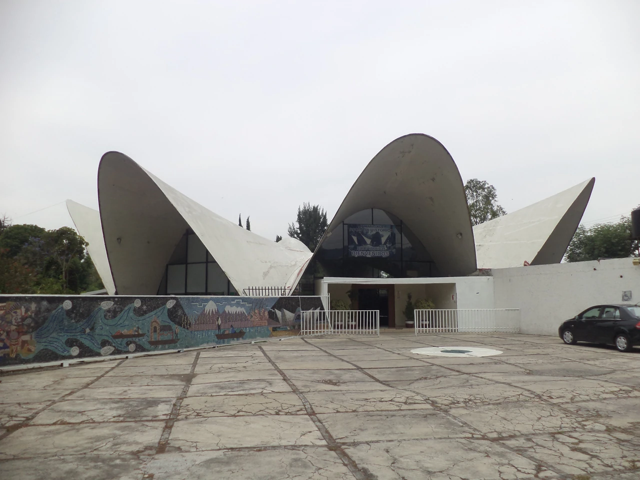
Félix Candela's shells offer another relationship between geometry and making. After exile from Spain brought him to Mexico, his work with Cubiertas Ala included industrial commissions as well as celebrated public forms. At Los Manantiales in Xochimilco, the 1958 restaurant replaced a timber building destroyed by fire in 1957. Joaquín Álvarez Ordóñez invited Candela's contribution. The building was a commission for dining and gathering, not an abstract mathematical surface without a social programme. [29]
Four intersecting hyperbolic paraboloids produce eight petals. Although the finished roof curves, ruled geometry allowed narrow straight timbers to form the temporary surface. Supports held that apparatus during construction. The shell's thinnest area did not describe the thickness everywhere: strengthened ribs and supports channelled forces towards the foundations. Geometry made a particular forming method possible, but did not eliminate reinforced details, temporary work or the need to transfer force at the edges. [29]

Text alternative for the diagram
Original generic ruled-surface illustration, not a traced Candela drawing, Los Manantiales petal reconstruction, structural model or formwork specification.
- A curved surface can use straight form boards
- Conceptual — not measured
- Ruled geometry
- This generic saddle is formed by a family of straight lines in space.
- Straight boards
- Straight temporary elements can follow one family of those lines.
- Support still needed
- Geometry does not remove supports, ribs or foundations.
Inside, dining, danzón and public gathering made the roof part of a lived interior. Its architectural achievement includes the room below and the relationship between supports, openness and activity. Reading it only as a picturesque flower would miss why the shell was made. Equally, seeing its curved surface does not reveal the hidden reinforcement or establish the present condition of its foundations. [29]
The university's 2025 restoration account makes those distinctions tangible. Subsidence, water extraction, the canal-bank setting and the 2017 earthquake affected support conditions; heavy later additions complicated the building's behaviour. Repair required work below the apparent sculptural surface as well as on it. The architectural form and the history of ground, water and intervention cannot be separated simply by concentrating on the roof's profile. [29]
Frames, walls and floors organise different interiors
Reinforced construction does not always mean columns carrying an otherwise free plan. Load-bearing walls take weight from floors and roofs, while a column frame concentrates support differently. A transfer slab can answer a change in column layout between levels. Each arrangement affects where space can remain open and where structure must continue. The practical question is which system makes a particular programme possible, rather than whether the material is generally capable of flexibility. [7]
| Arrangement | Structural and spatial relationship | Making or use distinction |
|---|---|---|
| Beam-and-slab frame | Beams connect supports and floors within a skeleton | Downstand members can affect partition heads and service routes. [7], [8] |
| Flat slab | A relatively uninterrupted soffit avoids downstand beams or ribs | Partition heads and services can meet or follow the floor differently. [8] |
| Ribbed slab | Band beams and narrower orthogonal ribs support a thin topping in the described arrangement | The underside reveals directional structure rather than a uniform solid plate. [9] |
| Waffle slab | Ribs run in both directions beneath a topping | Two-way geometry differs from a single set of ribs. [9] |
| Hollowcore floor | Longitudinal voids run through precast units | Units, optional structural screed and prestressed camber belong to assembly and subsequent loading. [10] |
| Crosswall system | Precast floors combine with load-bearing walls | Cellular programmes such as hotels and housing differ from freely partitioned column frames. [11] |
| Reinforced shell | A shaped surface works with ribs, supports and foundations | Forming geometry and temporary support help determine how the curved roof is made. [29] |
A flat soffit changes everyday coordination. Partitions can meet it without being cut around downstand beams or ribs; service routes do not have to negotiate the same projecting members. This is an architectural and building-services distinction, not a guarantee that every flat slab is thinner, faster or cheaper than every alternative. Support behaviour, openings and the demands of the complete building remain separate questions. [8]
Ribbed and waffle systems use geometry differently. The professional description of a ribbed arrangement combines broad band beams, orthogonal narrow ribs and a topping; waffle ribs run in two directions between column heads or band beams. Removing material from some areas changes weight and stiffness relative to an equivalent solid slab. The resulting underside can become an architectural feature, but its apparent pattern also belongs to a particular structural arrangement, not merely decoration. [9]

Text alternative for the diagram
Column arrangements are shown in elevation; the cellular wall arrangement is shown in plan. Original spatial silhouettes, not reinforcement drawings or comparable structural capacities. The table separately distinguishes ribbed, waffle and hollowcore floors.
- Support arrangements organise different spaces
- Conceptual — not measured
- Beam and slab
- Downstand members affect service routes and partition heads.
- Flat soffit
- A beam-free underside gives a different service and partition relationship.
- Cellular walls
- Plan
- Load-bearing walls organise rooms differently from a column frame.
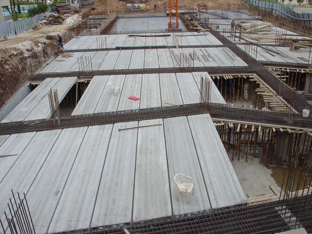
Hollowcore provides another form of selective material use. Longitudinal voids reduce unit weight and can accommodate services in appropriate arrangements. The smooth delivered soffit, optional structural screed and relationships between units make it an assembled floor rather than simply a solid cast plate with holes. Prestressed units can arrive with an upward camber that changes when additional permanent loads are applied. The shape at delivery is not necessarily the shape under the completed floor's later load. [10]
Precast, in-situ and hybrid construction
Precast is a manufacturing description, not a complete structural specification. Factory products include cladding, masonry, drainage, decorative objects and structural components. Some are reinforced or prestressed; the word by itself does not establish either. The difference between making an element elsewhere and casting a continuous arrangement in place also changes handling, storage, transport, temporary stability and connections. A finished building can combine both methods. [11], [12], [26], [32]
Wall systems make this mixture clear. Tilt-up construction casts walls on site, often on a floor slab or separate bed, before raising them into position. Twinwall combines precast leaves with reinforcement and concrete placed between them on site, with temporary props during the transition. Both involve movement and assembly, but neither can be reduced to the simple image of a finished factory wall arriving ready to function without further work. [11]
Other systems organise repeated casting. Tunnel forms allow walls and slabs of a cellular structure to be cast together, whereas insulating concrete formwork leaves insulating panels or blocks in place as permanent moulds. The permanent enclosure and temporary apparatus therefore overlap in different ways. A cellular hotel, a house wall and an open column frame need not share the same construction sequence merely because all contain reinforced concrete. [11]
The Japanese caissons and later precast prestressed bridges show that making place is inseparable from assembly. A component may be cast before transport yet require carefully organised joints and support before it becomes part of the final system. Repetition can be useful, but it does not eliminate the work at connections. The architectural unit, the transportable unit and the structurally continuous arrangement are not always the same thing. [26], [32], [33]
Prestressing changes the starting condition
Ordinary reinforcement is often described as passive because it participates as the member is loaded and deforms. Prestressing deliberately introduces a force before the full service loading acts, commonly using tensioned reinforcement to compress concrete. This active starting condition is the essential distinction. It does not mean that every part of every prestressed structure remains exclusively in compression under all circumstances, or that cracking and water protection cease to matter. [30], [32]

Text alternative for the diagram
Original passive/active contrast, not an exact stressing sequence, anchorage design, balanced force plot or promise that every part remains in compression.
- Passive reinforcement and active prestress differ
- Conceptual — not measured
- Ordinary bar
- No deliberate initial prestressing operation is shown in this comparison.
- Tensioned tendon
- Prestressing deliberately introduces force into the reinforcement.
- Concrete compressed
- Anchorage transfers that active force into the surrounding system.
Freyssinet's contribution developed through observation of concrete over time. The 1908 experimental arch at Moulins, associated with his Allier bridge work, investigated a restrained low-rise arch with a tie and anchored metal wires. Concrete's delayed deformation challenged an explanation based only on immediate elastic behaviour. Contractor François Mercier's support gave the young engineer opportunities to work through these questions. Experiments, commissioning and confidence helped prepare the later prestressing developments. [31], [32], [33]
AFGC's prestressing history dates Freyssinet's defining patent to 1928 and records précontrainte as terminology in January 1933. Earlier preloading ideas existed, but Freyssinet joined understanding of delayed deformation to material preparation and sustained force. The difference was not simply that metal could be pulled before a structure entered use: the initial compression had to remain effective as concrete changed over time. A patent year alone does not explain the achievement. [30], [32]
Prestressing also developed within resource pressures. Wartime priorities and later rationing shaped the appeal of concrete construction and economical metal use. The early-1930s Le Havre intervention and the realised Luzancy bridge, dated 1946 in the professional biography, belong to different applications and stages. Precast and prestressed assembly made particular slender forms possible, but a proposal, an intervention and the completion of a bridge are not interchangeable dates in one instantaneous invention. [32], [33]
Tendons and anchorages evolved together. Wire, strands and bars required compatible ways of transmitting and holding force; Freyssinet's 1939 concrete cone did not simply serve every later strand arrangement unchanged. Post-casting threading, ducts and injection also addressed friction and exposure during construction. These details connect active force to the building process. Prestressing is not an invisible magic ingredient added to an otherwise ordinary beam. [32]
Cover, water and corrosion
Concrete can protect embedded steel through its alkaline environment, which supports a passive state at the metal surface. Carbonation and incoming chlorides can disturb that protection through different mechanisms. Moisture, exposure, porosity, cracking and transport paths affect how the environment reaches reinforcement. Steel is concealed, but concealment alone is not protection; the surrounding material and details must continue to perform their roles. [1], [36]
Corrosion changes more than colour. Expanding corrosion products can crack or detach cover while metal loses section and bond deteriorates. The result connects the surface to an internal force-transfer problem. A spalled face is therefore not simply an aesthetic blemish, but neither can its appearance alone establish the complete condition of all reinforcement. The affected location, exposure and history require more than a general label of concrete decay. [3], [36]


Text alternative for the diagram
Original durability symbols, not identification of a pictured defect, numerical corrosion thresholds, a safety verdict or repair instructions.
- Embedded steel changes the meaning of cover
- Conceptual — not measured
- Protected metal
- An alkaline concrete environment can protect embedded steel.
- Protection changes
- Carbonation or incoming chlorides can disturb that protection.
- Cover / bond loss
- Corrosion can damage cover, metal section and force transfer.
Cracks need equally specific interpretation. Loading, shrinkage, thermal movement, restraint, settlement and corrosion can leave lines with different implications. Delayed deformation and temperature gradients also interact with how a whole structure is permitted to move. Joints and adjacent structures can concentrate restraint rather than releasing it. The fact that reinforced-concrete models include cracking does not supply a universal safe-width rule for a historic wall, floor or bridge. [2], [32]
Prestressed construction adds its own exposure history. The historical chapter describes water routes at joints, later-cast strips, tendon pockets and deck ends. Confidence in an apparently uncracked member could once encourage omission of waterproofing. Ducting and injection were developed partly to address exposed tendons and unreliable construction details. Passive bars and high-strength prestressing elements should not be presumed to have identical corrosion consequences. [32]
Limited favourable observations must retain their scale. The chapter's account of old Veurdre steel relates to particular examined material and a rain/runoff environment, not every tendon in every bridge or a present survey. Later conservation work can occur even where an earlier investigation described limited corrosion. Historic material survival is important evidence, but it does not stop time or remove the possibility of later strengthening. [31], [32]
Repairs can concern the whole system
Los Manantiales's restoration demonstrates why a curved roof cannot be conserved only as a thin surface. The university's February 2025 report describes temporary support, new piles and radial beams, followed by shell reconstruction that retained serviceable original reinforcement and recovered the ruled timber-form geometry. Work addressed ground, supports and roof together. The account credits architecture and engineering institutions, consultants, companies, government and workers on site rather than one solitary restorer. [29]
The restoration preserved the roof's architectural geometry while changing the support beneath it. Much of the work took place underground, beyond the surface that makes the restaurant immediately recognisable. In February 2025, Juan Ignacio del Cueto also described a possible landscape project linking nearby buildings and public spaces around the Zacapa landing. This remained a proposal. His argument connected the recovered structure to renewed social use: preserving a shell mattered beyond preserving its outline. [29]
The Moulins experimental arch has a different conservation sequence. Uncovering in 1993, protection in 2021 and strengthening between November 2025 and February 2026 were separate events; AFGC records inauguration on 20 February 2026. Preserving an experimental structure can include later intervention rather than freezing it at the moment of its original test. These dates also prevent an older condition description from becoming a claim that no work was subsequently needed. [31]
Retaining a frame is not merely recycling its rubble
Reinforced-concrete frames can have a different replacement cycle from windows, façades and services. Retaining the skeleton while changing shorter-lived layers preserves a structural resource in place. The Concrete Centre's examples include the conversion of the mid-1970s Camden Town Hall annexe into the Standard Hotel and a former Royal Mail sorting office into Northampton International Academy. They demonstrate changed programmes, not a promise that every existing frame can accept any new use without assessment. [37]
The CAP44 mill's later cladding and office use similarly separate structural survival from an unchanged exterior. A building can become visually unfamiliar while continuing to use an older concrete arrangement. Conversely, restoring an original-looking skin does not by itself restore every hidden structural connection. Appearance, programme and material continuity need to be considered together rather than treated as one measure of preservation. [17], [37]
Future disassembly is another question. Accessible, planned connections and separable components can help recover elements later; a monolithic frame cannot generally be imagined as a collection of pieces waiting to be unbolted. Retention, whole-component reuse and aggregate recycling preserve different amounts of an existing construction's form and work. Each may have a role, but they are not interchangeable explanations of circularity. [34], [35], [37]
Reusing structural pieces: realised arch, proposed housing
EPFL's Re:Crete prototype used 25 blocks cut from a cast-in-place concrete wall, assembled into an arch with two post-tensioning cables. Temporary centring and mortar accommodated the sourced pieces before the finished arrangement could take over support. The research team and industrial partners organised cutting, handling, assessment and assembly. Its 2021 opening and 2022 outdoor upgrade and Conthey installation were separate phases. Here reuse meant preserving structural pieces, not crushing them into aggregate for a new casting. [34]
An EPFL conference study by N. Widmer, M. Bastien-Masse and C. Fivet explored a different possibility: a theoretical six-storey housing structure using cut slabs and walls from two late-1950s Basel office buildings at the same site. It was a feasibility design, not evidence that the housing had been built. Available reinforcement and resistance helped determine which pieces could be allocated to new positions. The new building had to answer the stock of existing elements, not assume that arbitrary concrete rectangles were interchangeable. [35]

Text alternative for the diagram
Original distinctions between retention and two forms of recovery, not an EPFL figure trace, carbon percentage or declaration that a reclaimed piece is ready for use.
- Retention, component reuse and aggregate differ
- Conceptual — not measured
- Frame in place
- Keep a usable skeleton while changing other building layers.
- Whole component
- A recovered piece needs assessment and suitable new connections.
- Crushed aggregate
- Recover particles rather than the original structural arrangement.
Changed supports and joints also changed structural demands. Connections had to transfer chosen forces; slab deflection and punching, column behaviour and lateral resistance needed separate checks. The studied reuse arrangement used selective fibre-reinforced strengthening and new tied connections. A hybrid version made new core walls to simplify lateral resistance. These distinctions show why retaining material alone cannot establish that a new arrangement will work: the pieces and the complete system ask different questions. [35]
The study reported up to a 75 per cent reduction in greenhouse-gas emissions for its specified structural comparison. Its assessment covered a storey's structural system, donor demolition/disposal and selected construction stages; it did not include the new building's operation, maintenance or eventual end of life, and shared construction processes were excluded. Same-site storage meant that reclaimed-element transport was not included. These boundaries are essential to the result, not minor qualifications to a universal whole-building saving. [35]
Costs were similarly conditional. Comparable estimates depended on including donor demolition and disposal in the comparison; excluding those source costs made the reuse designs appreciably more expensive. Sawing and lifting dominated the studied reuse costs, while strengthening was a major contributor to the modelled emissions of reused variants. The estimates used 2021 Swiss prices with a stated precision of ±15 per cent, not a current quotation. Further investigation was still needed. Reuse's architectural promise is strongest when its material, connections, labour and assessment boundaries remain visible. [35]
Reinforced concrete does not dictate one society or style
The recurring distinction is between a capability and the conditions under which it is used. A frame can permit larger openings without abolishing household hierarchy; standardised equipment can accompany a proposed free plan; local supply or regulation can constrain a system developed elsewhere. A shell can create a remarkable interior while remaining dependent on temporary forms, supports and foundations. Structural innovation changes the available questions, but does not provide one automatic answer to each commission. [14], [22], [23], [24], [25], [26], [27], [28], [29]
Priyanka Shah's 2008 MIT master's study considers the concrete frame as a spatial resource in Mumbai, relating its use to plot scale, density and redevelopment and asking about production by developers, architects and artisans. This perspective separates the skeleton's structural possibilities from the urban circumstances in which they are used. A frame does not organise a city independently of the people and institutions deciding what to build. [38]
From a wire-supported container to a reused wall block, the most useful history follows the actual combination of materials, the way it was made and the programme it served. Reinforced concrete's importance is not that it ended the need for other materials or made every form equally straightforward. It gave architects, engineers and builders a family of structural possibilities whose consequences depend on arrangement, execution, institutions, use and care over time. [1], [14], [16], [17], [25], [27], [34], [35], [36], [37]
About the Recommended Reading
Aesthetics and Technology in Building: The Twenty-First-Century Edition — Pier Luigi Nervi
The University of Illinois Press's 2018 edition, edited by Cristiana Chiorino, Elisabetta Margiotta Nervi and Thomas Leslie, connects architectural form with practical construction questions. The publisher describes Nervi's lectures alongside additional scholarly essays and illustrations. It is a useful companion for readers interested in how precast and cast-in-place methods entered an engineer's architectural thinking. [40]
Cascarones de Candela / Candela's Shells — Juan Ignacio del Cueto Ruiz-Funes
UNAM's bilingual 72-page publication, first issued in 2016, offers a focused route into Candela's shell work rather than a general survey of every concrete system. The Spanish-and-English format is particularly useful alongside the account of ruled geometry, industrial commissions and the Los Manantiales restaurant. [39]
Auguste Perret — directed by Joseph Abram
The French monograph recorded by the BnF examines Paris work before 1940, including Franklin, the Champs-Elysées theatre, Salle Cortot and Raincy. The 2013 Éditions du Patrimoine edition provides a reading path through an architect-builder's varied programmes, showing why reinforced concrete should not be equated with one bare-surface style. [41]
Watch: shells, reuse and an experimental arch
UNAM's restoration account, EPFL's Re:Crete prototype and an AFGC-linked heritage film explore different histories of reinforced construction.
La UNAM encabeza la restauración de una joya arquitectónica en Xochimilco
The university's Los Manantiales film accompanies its account of restoring the shell and its supporting system.
Loading connects to the original film provider. No film is loaded before you choose to load it. The preview is an abstract editorial symbol, not a film still.
Watch at original sourceAbout the Films
La UNAM encabeza la restauración de una joya arquitectónica en Xochimilco — UNAM Global TV
The university's film accompanies its Los Manantiales restoration account. It offers a visual counterpart to the discussion of a shell whose preservation involved ground, supports, reinforcement and forming geometry, rather than simply renewal of the visible surface. [29]
Concrete footbridge without pouring concrete — EPFL
EPFL's film introduces the Re:Crete prototype. Follow it alongside the distinction between retaining cut structural pieces and recycling aggregate: the arch represents a new assembly made from existing concrete components, with new connections and active force. [34]
Arche d'essai Freyssinet à Moulins — Emmanuel Baillia
This heritage film, uploaded by Emmanuel Baillia and linked from AFGC's arch record, concerns the experimental structure associated with Freyssinet's early work. Its title's priority claim should be read alongside the wider history of preloading and the carefully dated account of experiments and later preservation. [31], [32]
Frequently Asked Questions
No. Reinforcement needs an intended position, continuity and anchorage, with bond transferring force to and from surrounding concrete. An arbitrary amount of metal does not establish a working composite. Historical experiments also used iron, wire rope and matrices that were not all equivalent to a modern specification. [1], [3], [14]
Not completely. Reinforcement can influence crack distribution and carry forces across cracks, while concrete between cracks can still contribute through bond. Loading, shrinkage, temperature, restraint and corrosion can produce different cracking histories. Anticipated cracked behaviour does not mean any visible crack is automatically harmless. [2], [3]
Ferrocement combines hydraulic-cement mortar with distributed continuous fine mesh. Ordinary reinforced concrete commonly uses a coarser aggregate matrix with positioned bars or other reinforcement. Both involve composite action, but their reinforcement arrangement and making should not be treated as one interchangeable material description. [1], [4]
Not automatically. Different metal, mineral and polymer fibres have different roles, including effects on fresh cohesion, cracking, ductility, wear or fire behaviour. A fibre-containing mix does not supply every function of every designed bar arrangement merely because it contains dispersed reinforcement. [5]
There is no useful single answer covering every object, matrix, floor, patent and complete commercial system. Lambot, Monier, Wilkinson, Hyatt, Coignet, Hennebique and others made different contributions. Dates become meaningful when they identify what was patented, tested, proposed or actually constructed, rather than assigning universal priority to one name. [13], [14], [15], [16], [17], [18], [19], [20]
It can separate some supports from partitions, but programme, circulation, services, enclosure and regulation still shape the plan. Franklin retained household hierarchies within a new frame; Dom-Ino paired structural freedom with standard equipment. A capability is not a completed architectural or social programme. [14], [22], [23], [24]
No. Precast describes production before delivery or assembly and includes many structural and nonstructural products. Prestressing describes a deliberately introduced force. A particular component may be both, either or neither; its identity requires more than the place where it was cast. [10], [11], [12], [30], [32]
In a ruled geometry, it can. Los Manantiales's intersecting hyperbolic paraboloids permitted narrow straight timbers to form a curved temporary surface. That geometrical advantage did not remove temporary supports, reinforced details, ribs or foundations. The method belongs to a particular shell rather than every possible curved roof. [29]
Concrete's alkaline environment can protect steel, but carbonation and chlorides can disturb that protection. Moisture and transport through pores, cracks and details affect exposure. Corrosion can damage cover while reducing metal section and bond; concealment alone cannot guarantee the reinforcement's condition. [1], [36]
No. Retaining a frame preserves it in place; reusing a cut slab or wall preserves a component in another arrangement; crushing it recovers material as aggregate. Connections, available reinforcement and the new system need assessment. Carbon and cost comparisons remain specific to their transport, strengthening and accounting assumptions. [34], [35], [37]
References
- Infociments/Cement Lab. Notions de dimensionnement du béton armé : dispositions constructives pour les armatures.
- Infociments/Cement Lab. Fissuration des ouvrages en béton armé : généralités.
- Michael Auer. Ein Verbundmodell für Stahlbeton unter Berücksichtigung der Betonschädigung, KIT dissertation, 2015, 1–4, 51–55, 90–91 and 225–227.
- Food and Agriculture Organization. Ferrocement boatbuilding: introduction, chapter 1, sections 1.1–1.2.
- Infociments. Fibres, April 2018.
- Concrete Masonry and Hardscapes Association. Glossary of Concrete Masonry Terms, TEK 01-04.
- The Concrete Centre. Building elements and Floors.
- The Concrete Centre. Flat slabs.
- The Concrete Centre. Ribbed and waffle slabs.
- The Concrete Centre. Hollowcore slabs.
- The Concrete Centre. Walls.
- The Concrete Centre. Precast.
- Thaddeus Hyatt. An Account of Some Experiments with Portland-Cement-Concrete Combined with Iron, London, 1877, 3–28 and plates A, G–I.
- Patricia Cusack. Reinforced Concrete in Britain: 1897–1908, University of Edinburgh PhD, 1981, volume 1, 15, 48–61 and 219–226.
- Communauté d'agglomération Provence Verte. Magazine été 2025, 56–57.
- AFGC. Joseph Monier.
- Bernard Raspaud, Georges Pilot and Noël Richet. François Coignet, Edmond Coignet, François Hennebique, Auguste Perret : ingénieurs et constructeurs français, IESF, March 2023.
- AFGC. François Coignet.
- Cité de l'architecture et du patrimoine. François Hennebique.
- AFGC. François Hennebique.
- Cité de l'architecture et du patrimoine. Hennebique and French architects in Berlin.
- Cité de l'architecture et du patrimoine. Rue Franklin.
- Cité de l'architecture et du patrimoine. L'immeuble de la rue Franklin : dossier pédagogique.
- Fondation Le Corbusier. Maisons Dom-Ino, 1914.
- Shu Jianshuo and Takahiro Taji. Study on the Development of Reinforced Concrete in the Department of Architecture of Japan from the Ending of Russo-Japanese War to Great Kanto Earthquake (1906–1923): Research on Certain Textbooks and Magazines of the Era, AIJ Journal of Architecture and Planning 87(796), 2022, 1050–1061.
- Yamashita Ikuhiko and Fukute Tsutomu. 鉄筋コンクリートの歴史—港湾構造物—, Journal of the Japan Society of Civil Engineers, 1992(442), 1–7.
- Juan Pablo Pekarek. Hennebique en la obra del Estado argentino : renovación técnica y tradición francesa del hormigón armado (1911–1915), Limaq 12, 2023, 49–74.
- MAXXI. Pier Luigi Nervi : architetture per lo sport, 2016.
- UNAM Global. La UNAM encabeza la restauración de una joya arquitectónica en Xochimilco, 20 February 2025.
- AFGC. Le béton précontraint.
- AFGC. Arche d'essais du pont du Veurdre par Eugène Freyssinet.
- Historique du béton précontraint, chapter 1 of La pérennité du béton précontraint, 11–18, provided by AFGC.
- AFGC. Eugène Freyssinet.
- EPFL Structural Xploration Lab. Reuse of concrete : Re:Crete.
- N. Widmer, M. Bastien-Masse and C. Fivet. Building structures made of reused cut reinforced concrete slabs and walls: A case study, in Life-Cycle of Structures and Infrastructure Systems, 2023, 172–179.
- Patrick Guiraud / Infociments. Prévention des phénomènes de corrosion des armatures en acier dans le béton, April 2018.
- The Concrete Centre. Refurbishment, reuse and renewal.
- Priyanka Shah. Master's thesis on concrete-frame architecture in Mumbai, MIT, 2008, abstract.
- Juan Ignacio del Cueto Ruiz-Funes. Cascarones de Candela / Candela's Shells, UNAM, 2016.
- Pier Luigi Nervi. Aesthetics and Technology in Building: The Twenty-First-Century Edition, edited by Cristiana Chiorino, Elisabetta Margiotta Nervi and Thomas Leslie, University of Illinois Press, 2018.
- Auguste Perret / Joseph Abram, BnF Salle Ovale, and Grenoble's municipal catalogue, 2013 Éditions du Patrimoine edition, ISBN 9782757703762.
Explore RELATED Architecture
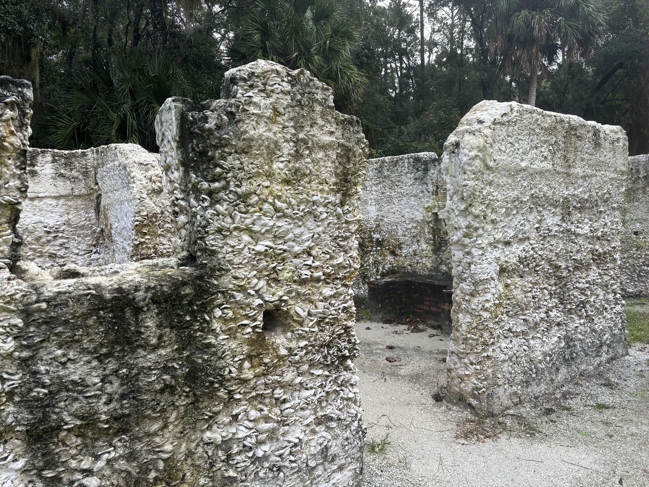
Concrete
Follow the material's binders, casting and surfaces separately from the reinforcement system embedded within it.
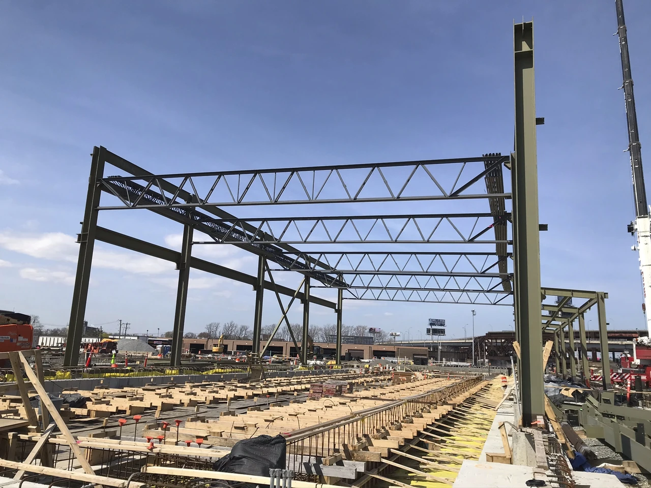
Steel Frame
Compare a skeleton of metal members with the interaction between bars and their surrounding concrete.
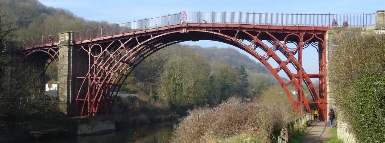
Cast Iron
Place nineteenth-century metal construction beside the fire and economy questions that encouraged composite floors.
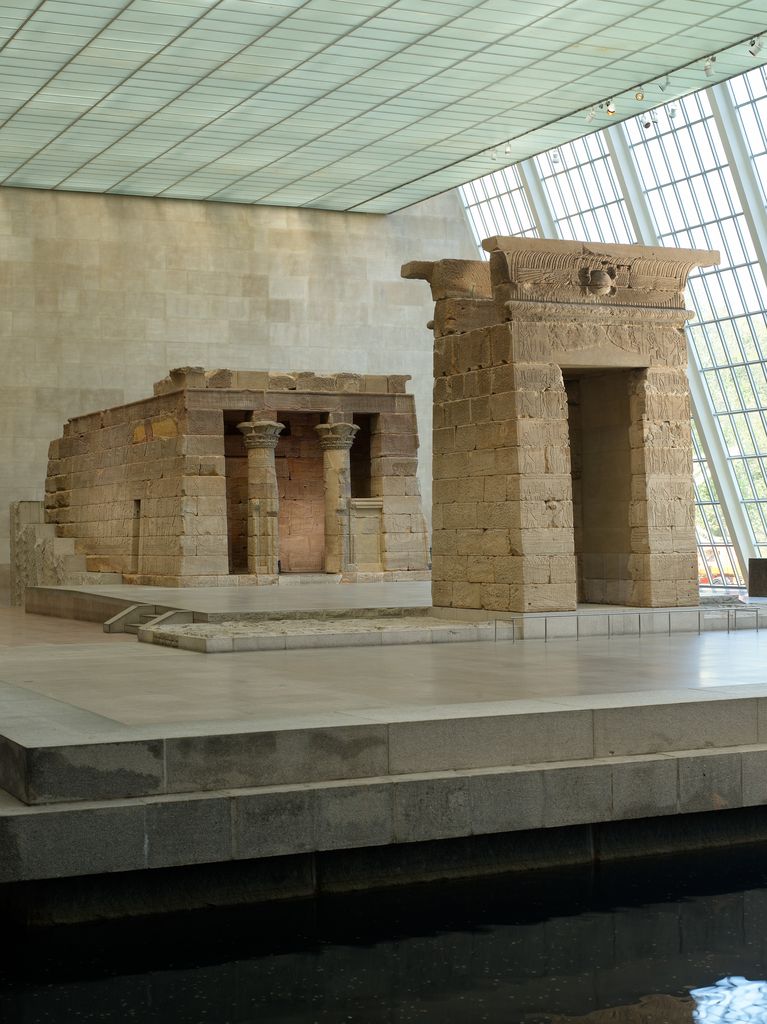
Columns
Consider concentrated support as an architectural element, rather than assuming every visible column uses the same internal system.

Domes
Compare the geometry of a roof with the material and structural arrangement used to build it.

Colonnade
Explore repetition, rhythm and covered circulation alongside the spaces organised by a reinforced skeleton.
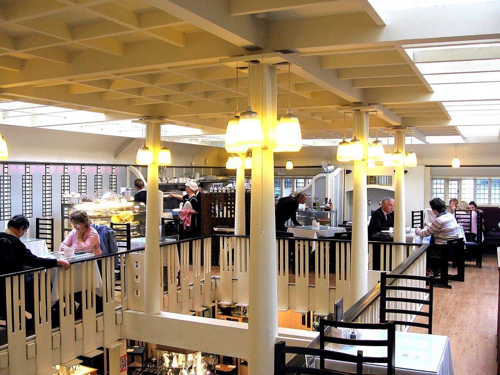
Art Nouveau
Read the ornamental context of the ceramics and decorated façades associated with early reinforced construction.
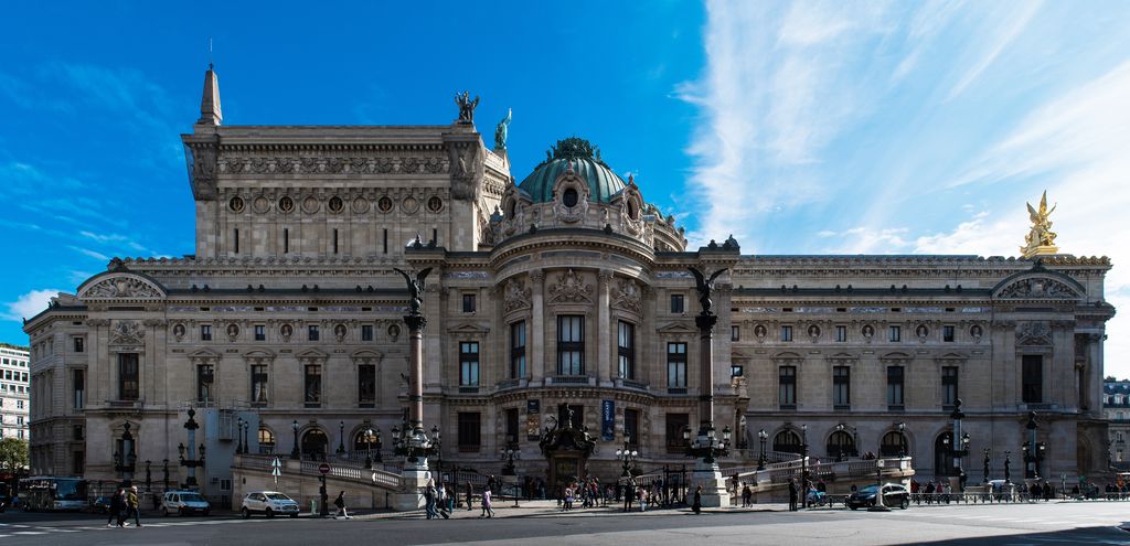
Beaux-Arts
Compare the planning and compositional conventions that continued, or were questioned, as reinforced systems spread.