


 by Tom Gurney
Tom Gurney BSc (Hons) is an art history expert with over 20 years experience
Email: tomgurney1@gmail.com / Phone: +44 7429 011000
Face, Proposal, Record and Reader
An architectural elevation looks at one face of a building or architectural element. It sets openings, rooflines, orders and materials into a vertical relationship that a floor plan cannot show. Yet “looks at” should not be mistaken for “photographs”. An elevation is a constructed drawing: it chooses a face, projects it into a plane, suppresses or clarifies depth, and may show a building still imagined, a design being revised, a structure already altered, or a ruin measured centuries later. A finely coloured frontage can be an argument to a patron; a spare line sheet can guide a mason; a printed Gothic pinnacle can transmit geometry; a later survey can document lean and lost fabric. The same apparent frontality carries different evidence. [1], [2], [3], [9], [10], [11], [28], [31], [32], [33]
The question is not simply whether an elevation is accurate. Accurate about what? The proposed appearance, a particular construction stage, an existing wall at survey date, or the arrangement a publication wanted readers to remember may differ. Front, side, rear and interior elevations need not have equal attention or equal archival survival. A doorway can be drawn ornamentally before its mechanism is determined; a porch can hide wall that a measured survey must record separately. Makers, clients, copyists, printers and later surveyors can each change how the same facade enters the record. These histories make elevations unusually rich witnesses to architecture, but only when their date, status and accompanying views are read together. [1], [11], [14], [22], [25], [28], [29], [32], [33], [34], [35], [36]
At a Glance
- What it showsThe visible arrangement of one exterior or interior face, normally without the converging lines of perspective. [30], [31], [32]
- First questionIs this a proposal, working drawing, printed plate, later artist’s rendering or measured record? [1], [14], [18], [31], [32]
- Reading keysIdentify the named face, datum, scale, heights, openings, line weight, material notes and revisions. [30], [32], [36]
- DepthRecesses and projections may need a plan, section, true side detail or photographs to be understood. [1], [13], [28], [32], [33]
- Other facesFront, side, rear and interior views may differ in finish and survival. [22], [24], [25]
- HistoryA compelling facade proposal does not prove that all its details were built. [9], [10], [18], [19]
- EvidenceA survey date, original design date, later copy and digitisation date are not interchangeable. [14], [24], [25], [31], [32], [33], [34], [35]
- MaterialsWash, graphite, ruling and scale marks can reveal how a proposed face was developed. [7], [8], [9], [17]
Contents
- A face projected, not a photograph of the whole building
- Gothic elevations: fragments, craft and publication
- Renaissance elevations and the problem of a single view
- Wash, facade rhetoric and the patron’s choice
- Makers, fronts and the built question
- Exterior, interior and the detail that a facade cannot carry
- Japanese drawing archives and unequal completeness
- The elevation made after the building
- Drawing survival, design history and what to compare
A face projected, not a photograph of the whole building
An elevation typically projects a wall or building face orthogonally onto a vertical plane. Unlike a perspective, parallel horizontal edges need not converge toward a vanishing point. Openings can be compared across bays; cornices and sills can be aligned; a roof profile can be related to a wall below. A front elevation may be the most familiar, but side and rear views can tell another story, especially where a site slopes or a wing projects. Spanish architectural-drawing pedagogy distinguishes alzados from plans and sections, and describes the exterior face as a place to judge composition and fit with the surrounding environment. A later Spanish measured-drawing paper expressly allows an alzado of an interior face. The word therefore identifies a manner of facing an architectural plane, not only the building’s street front. [30], [31]

Text alternative for the diagram
Two invented fronts contrast a parallel orthographic projection with a receding perspective. Neither reproduces a historical source drawing.
Frontality has a price. A portico before a wall can obscure openings; a balcony may hide the part of a facade behind it; a projecting polygonal bay may be shortened in the principal view. Lines and wash can suggest depth but cannot make all three-dimensional relations unambiguous. A plan locates the projection, a section can show its height and attachment, and a detail can show its assembly. HABS measured-drawing guidance, for example, advises a separate straight-on detail where a bay’s angled side wall would be foreshortened, and separates an obscured wall from a porch or roof overhang so that each can be measured clearly. Those are practical conventions for a particular US survey tradition, not rules by which a fifteenth-century parchment must be judged. [1], [13], [28], [32]
The term itself has a history. The Bibliothèque nationale de France calls one Boullée funerary sheet an élévation géométrale, a geometric view; another Boullée arch record is catalogued as an élévation perspective. The labels remind us that “elevation” in historical catalogues can be attached to a persuasive, perspective-inflected image as well as a strictly orthogonal projection. We can describe the conventional method without rewriting archival language into a false single meaning. [20], [21]
Gothic elevations: fragments, craft and publication
Large Gothic drawings were not merely decorative pictures of completed cathedrals. The Met’s Gothic draftsmanship research places portal, tower, window, vault and liturgical-object designs within craft practices of geometry, proportion and communication. Its gallery juxtaposes partial facade elevations, elevations paired with plans, component studies and alternative tower schemes. Many of those medieval sheets are on loan from European collections. In a 2022 curatorial account, Femke Speelberg discussed around 600 surviving late-Gothic architectural drawings in the corpus she was examining and their strong concentration in Vienna, Ulm and Strasbourg institutional holdings. That was an account of a particular European survival, not an absolute world total. A working sheet used hard on a site and one protected in a lodge or archive did not have the same chance of survival. No one surviving Western sheet can establish an invention date for architectural drawing everywhere. [2], [37]
One fragment in The Cloisters makes uncertainty tangible. Robert Branner described a fifteenth-century French vellum with portions of two portal fronts. The apparently open central portal and a decorated but blind portal to the left cannot be read as identical entrances simply because both are framed on the facade. A later French inscription and nineteenth-century facsimile point to a once wider, probably joined parchment whose missing parts deny a secure full reconstruction. Branner judged the unusually fine execution and paucity of obvious construction marks consistent with a drawing presented to a patron, but this is an interpretation. The building, architect, full upper composition and possibility of an accompanying plan remain unknown. The elevation is evidence of a designed face, not a licence to invent the church it supposedly recorded. [1]

Text alternative for the diagram
An invented blind arch-like front and separate plan opening illustrate why Branner’s Cloisters portal distinction needs other evidence; the drawing is not a reconstruction of that vellum.
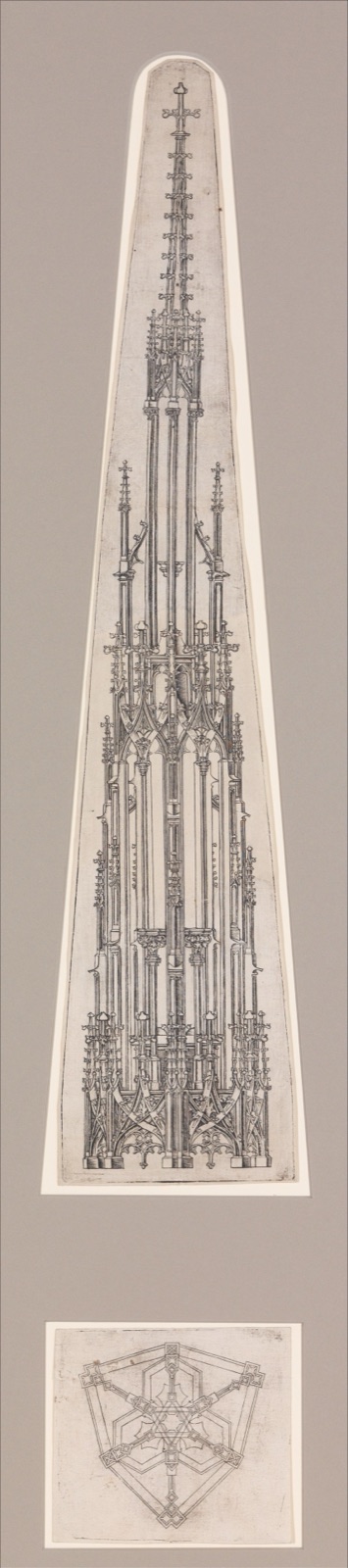
The printed image of a Gothic pinnacle by Wenzel von Olmütz is a different kind of witness. Beneath its extraordinary vertical tracery sits a small hexagonal plan. The engraving, dated by the Met to 1490–99, carries building-lodge geometry into a reproducible medium. It is associated with late-Gothic Ulm design traditions, but it is not the original site parchment of a named tower. The relationship between the compact plan and soaring face matters: the plan can fix a footprint or rotational scheme; the elevation elaborates vertical succession. A modern Met animation based on Matthes Roriczer’s 1486 publication demonstrates how plan geometry can be developed into a pinnacle elevation. Its application to an unrealised sacrament-house model is a present-day reconstruction, not footage of medieval masons at work. [3], [4]
The Met’s monumental sacrament-house parchment associated with Lorenz Lechler gives this collaboration a name and physical scale. Inscribed 1502, it is about 3.23 metres high but only 36.5 centimetres wide. The museum distinguishes Lechler’s architectural elevation from the sculptural programme of an unidentified Central European artist; blind ruling lies beneath two kinds of ink, and a seventeenth-century inscription belongs to its later life. The intended church is unknown. The drawing’s extraordinary vertical reach could present a daring internal church structure to a patron as well as help organise craft work, but its size does not prove the project was executed where we might imagine. It is neither a purely autonomous artwork nor a complete written building instruction. Material, scale, marks and later use condition what it can tell us. [2], [37]
Renaissance elevations and the problem of a single view
Renaissance elevation-making could combine rigorous projection with imagination about decoration and movement. Cigoli’s late-sixteenth- or early-seventeenth-century facade sheet, held by the Met, is made in ink and brown wash over preliminary lines. It presents fragments of portals, niches, figural ornament and a larger wall rhythm in one tall study. The catalogue names no building whose completed front the sheet measures. Its divisions suggest thinking through alternatives or adjoining episodes, but they cannot be turned into a documented construction sequence from the image alone. It is also not the separate Cigoli/Buontalenti drawing for the 1589 Florence cathedral-facade competition discussed in a Met curatorial essay. Similar artist names do not make two sheets the same project. [7], [17]
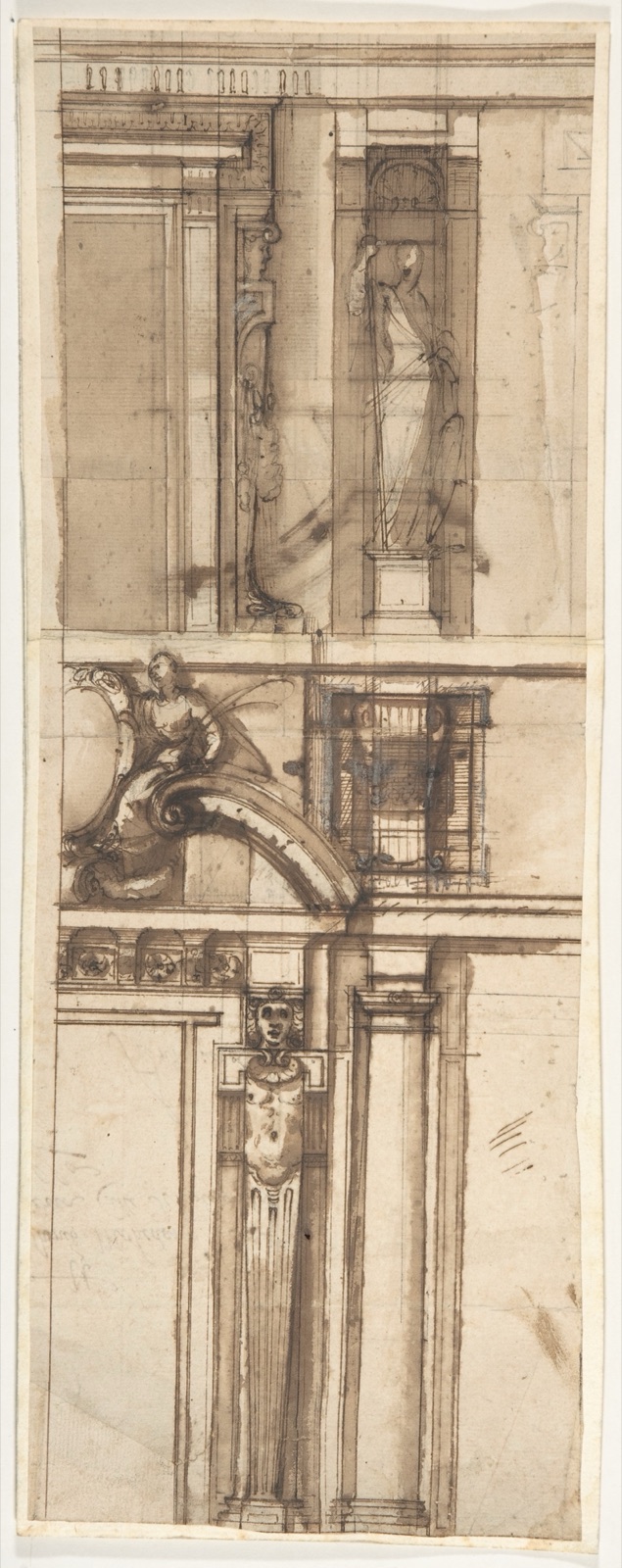
The curators’ comparison of an orthographic Florence cathedral proposal with a three-dimensional model reveals another elevation role: a drawn face can compete to persuade patrons of material, shadow and ornament even while geometry is controlled. They also describe Italian interior-decoration sheets whose drawn wall continues into vault and lunettes when paper is folded or curved. A flat frontal rectangle may be one part of a spatial surface, and the physical sheet can invite three-dimensional reading. A visitor who sees only a cropped facade reproduction may miss the lines, edges and paired views that made the proposal intelligible. [17]
Andrea Palladio’s printed architecture offers a more subtle case. In I Quattro Libri dell’Architettura, some plates join half of an exterior elevation to half of an interior section. The pairing can place an outside cornice, window or roof against the interior member at its height, while using symmetry to let the reader imagine the whole. In a full TU Berlin study of the book’s drawings, Lorena Cristina Valdivia Steel identifies fourteen such combined views among eighty-six analysed published objects, but only seven meet the strict same-sheet, same-scale relationship associated with Raphael’s scheme. The rest vary in layout or scaling. The device is instructive because it exposes the problem a pure front cannot solve: how exterior order relates to interior height. It would be wrong to call the half-elevation/half-section a universal Palladian template. [28]

Text alternative for the diagram
Two invented half-views line up an outside sill/cornice with inside floor/height. They explain, without reproducing, selected Palladio plate arrangements.
The book page could change the comparison. Front and back views of Palazzo Porto occur on opposite sides of a leaf; a reader seeing them together in another edition or digital spread might misconstrue them as halves of one facade. Other plates place views on facing pages or turn a plan. Translation, reproduction and page turning are therefore not neutral containers for architectural evidence. They shape which elevations appear adjacent, comparable or authoritative. A published plate is a historical object of editorial design as well as a drawing of architecture. [28]
Wash, facade rhetoric and the patron’s choice
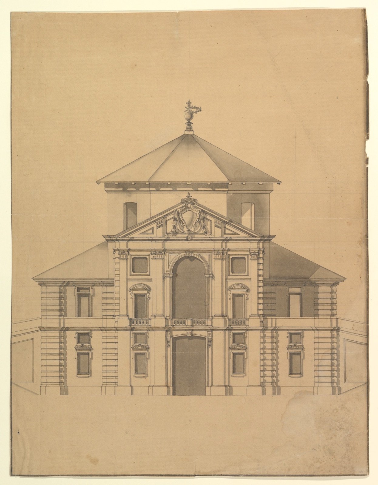
An eighteenth-century elevation could communicate appearance through washes without being a measured record. The Met’s anonymous Piedmontese sheet for an octagonal-cupola building retains leadpoint or graphite preparation, ruled and compass construction beneath grey ink and wash. The tonal surface makes masses and roof forms legible, while the earlier marks show that visual finish and geometric labour coexist. Its catalogue gives a wide date range, 1700–80, and no secure built site. It is a proposed building face in the museum record, not a photograph of an eighteenth-century town. [8]
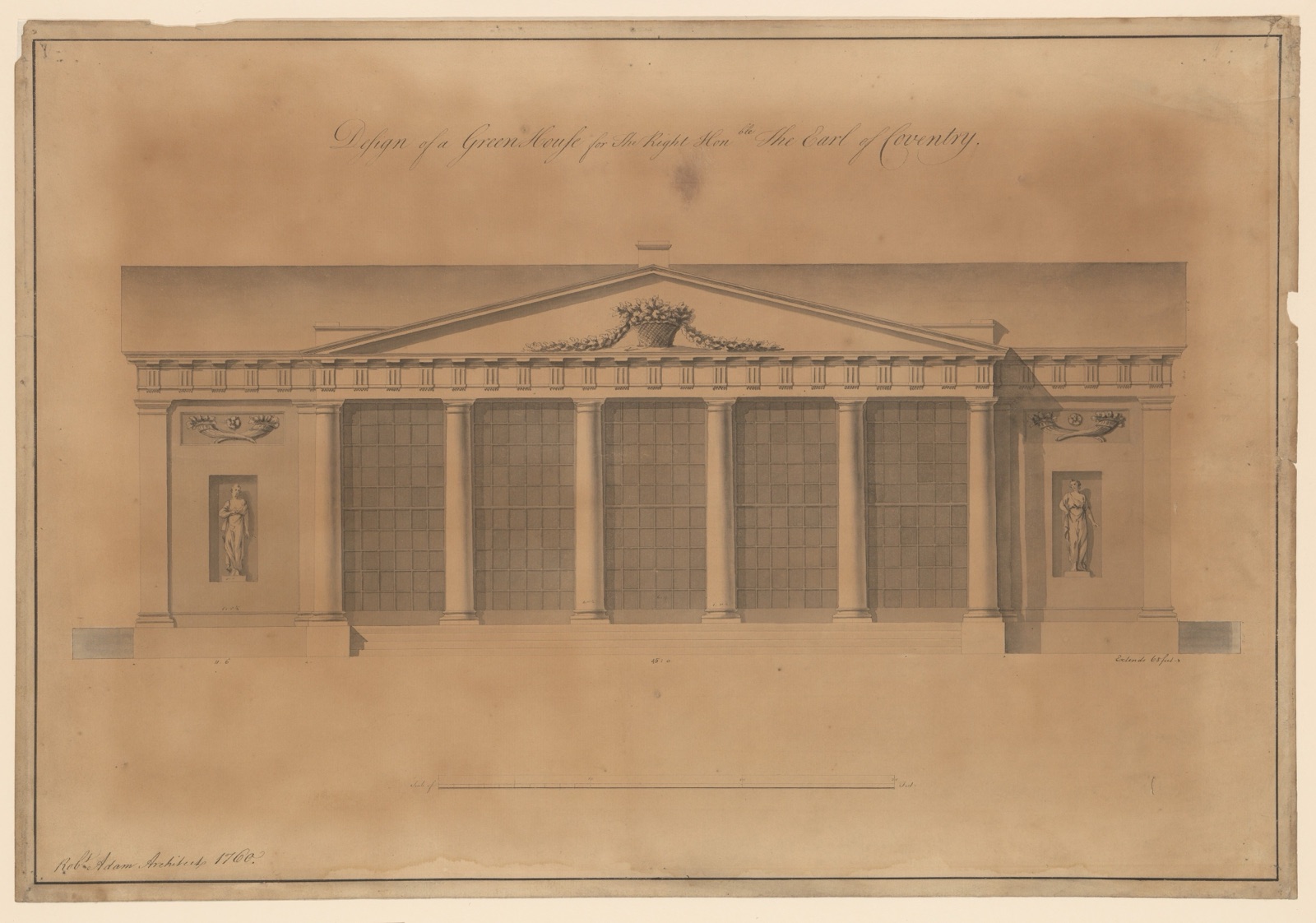
Robert Adam’s 1760 design for a greenhouse at Croome Court has a very different documentary foothold: a named architect, named patron and named estate. The long front sets glazed bays into a measured-looking rhythm under classical ornament. The large sheet would let a patron grasp how the horticultural building might sit as an architectural frontage, not just a utilitarian glass enclosure. Its title identifies a design for the Earl of Coventry; the museum record alone does not certify that every window, statue or roof detail was built as drawn. The elevation can be read against the landscape and against other Croome records, but its communicative status remains that of a specific proposal. [9]
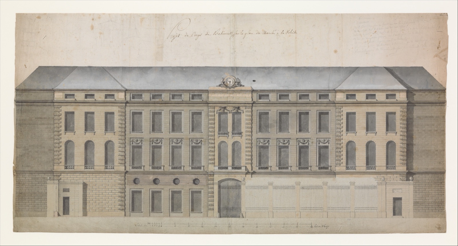
Facade-making was not always about a single entrance. A French drawing of the Paris Marché à la Volaille stretches across a broad urban front. Célestin-Joseph Happe’s coloured washes mark differentiated bays, roof and central emphasis, but a horizontal street elevation can also show how an institution presents itself to city life. Its eighteenth-century attribution gives no exact drawing year and no stated survey method. The image is therefore useful for reading civic composition and visual hierarchy, not for proving exact execution on the Quai des Grands Augustins. [10]
Boullée’s designs for a library frontage take persuasion further. The BnF catalogues a signed 1788 rue Colbert entrance elevation with Atlas figures supporting a globe beside the door. It belongs to a numbered restoration project for the Bibliothèque nationale, and related large elevation sheets have different labels and arrangements. One is catalogued Élévation non assujettie; preserving that title is more honest than assigning it a single English meaning without the project context. What the signed sheet can prove is an architect’s proposed symbolic treatment and a documented date inscribed on that drawing. A group of alternative elevations does not, merely by surviving, tell us which one was executed, or that an existing entrance resembled their solemn washes. Boullée’s funerary architecture ensevelie drawing makes the distinction especially clear: a precise geometric elevation can still be visionary architecture rather than a record of masonry. [18], [19], [20], [21]

Text alternative for the diagram
Three schematic record boxes distinguish a dated facade proposal, possibly altered building, and later observed measured record; not an inevitable chronology for every project.
Makers, fronts and the built question
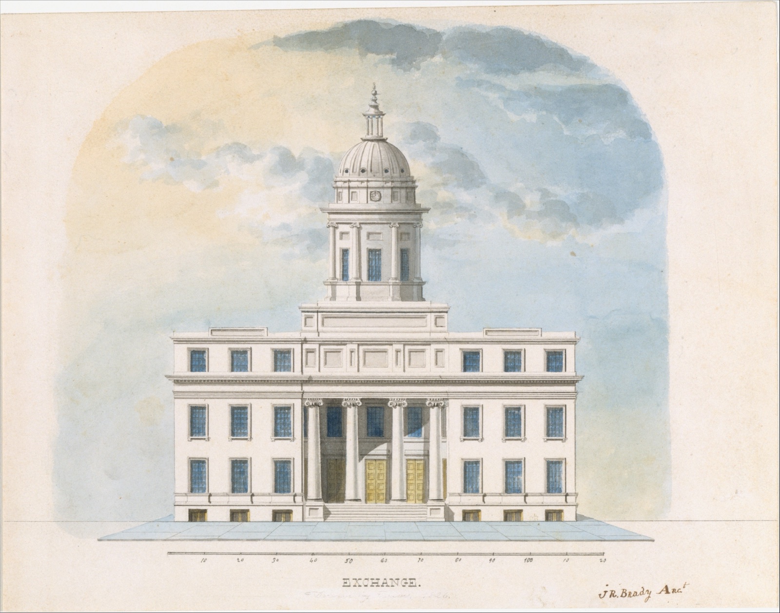
Sometimes the person who draws the elevation is not the person who designed the building. The Met identifies Alexander Jackson Davis as the draughtsman of an elevation for New York’s First Merchants’ Exchange, probably made in 1826, while naming Josiah R. Brady and Martin Euclid Thompson as the architects. Davis’s watercolour gives the facade blue windows, a central cupola and a presentation sky; it is visually memorable. But to write “Davis designed this exchange” from the sheet’s maker field would erase the explicit design attribution. Drawing, designing, commissioning and later publishing can be different acts. [11]
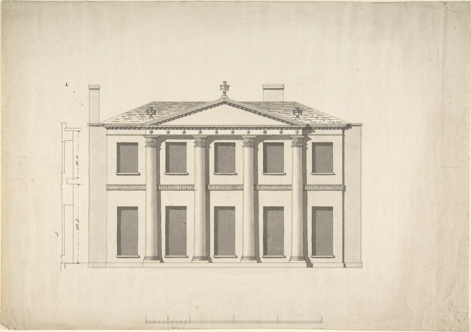
An anonymous eighteenth-century British five-bay facade sheet pairs an elevation with a wall-plan strip. The plan and scale can locate the portico’s projection or wall line while the front shows the column order, pediment, chimneys and openings. Neither sheet nor catalogue names a site, client or executed building. That absence is an important fact about evidence: a drawing can show a coherent scheme without giving a historian authority to attach it to a house by visual resemblance. The combined face/plan is still valuable because it lets us understand a portico as spatial structure rather than a facade ornament floating in a flat picture. [15]
Davis’s far sparer entrance-front drawing for the Chamberlin House in Red Hook, dated 1849 in the Met catalogue, also carries a scale. Its restrained outline makes the width of bays and relation of entrance to wings clear without supplying the space behind those walls. Colourful watercolour and spare linework are different presentation choices, not automatic proof that one building was more fully designed than the other. [12]

Text alternative for the diagram
An invented facade and wall-plan footprint show how a portico projects; not a copy of the anonymous British Met sheet.
The Politecnico di Milano Bottoni archive offers an instructive contrast. For an academic 1922–23 memorial exercise it lists front, rear and side studies at 1:50, together with a larger signed panel of plan, elevations and perspective. A 1924 palace exercise has a full elevation at 1:200 among drawings at other scales. These are traces of training and design testing, not evidence of commissions for actual monuments or palaces. The archive’s later Bottoni-and-Pucci Parma house record connects an asymmetrical, coloured bay frontage to an L-shaped plan, garden trees and the rhythm of a residential street. It argues for facade design as a negotiation with setting rather than a detached two-dimensional pattern; the proposed palette still cannot be promoted to an as-built paint survey without additional evidence. [22], [23]
Exterior, interior and the detail that a facade cannot carry
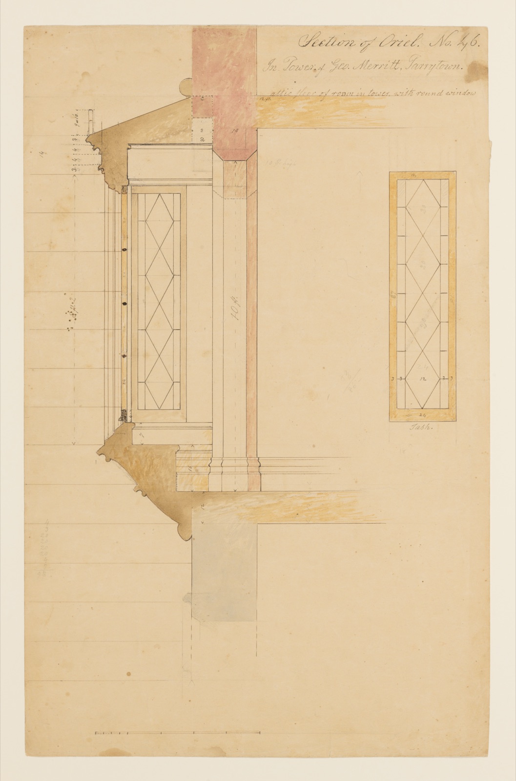
The principal building front is only one level of design information. A door, window, stair or cornice can need its own elevation at a larger scale, with a section or plan beside it. The Met’s technical Lyndhurst sheet attributed to Davis visibly combines a drawn window-like opening, adjoining section, dimension marks and a second face/detail. Its catalogue title and narrative disagree about whether the project feature is an oriel window or sliding dining-room doors, so the safest visual claim is narrower: the sheet demonstrates that a small part of a larger facade can demand several views to communicate construction. It does not license an invented account of the mechanism or room from the image alone. [13]
Contemporary working-drawing guidance speaks to this dependence. An elevation has to agree with plans, sections, detail references and specifications about heights, openings, structural relationships and materials. Revised window positions need to be legible across a drawing set, not just corrected in one attractive front. The AIA’s quality-control checklist is a member-contributed, non-exhaustive professional guide; it helps explain present-day coordination, not the exact obligations of a medieval architect. A Spanish CAD teaching exercise likewise draws four orthographic faces and a roof plan from one invented three-dimensional object. Its four alzados make differently oriented faces comparable, but the exercise is pedagogical and cannot be cited as experimental evidence that every public reader understands elevations in the same way. [30], [36]

Text alternative for the diagram
Four invented facade strips are labelled front, right, rear and left; these do not describe any recorded historic building.
Interiors challenge the street-front bias still further. An interior elevation can describe a wall of shelving, an altar screen, a room’s panelling or a stair-facing surface. Its datum may be floor or another consistently defined level; its sections show how the finish attaches and how a window meets the wall. The Spanish survey literature names this interior possibility explicitly. Historical sheets may be decorative or spatial, and the Met’s folding examples show that an interior wall elevation can continue onto a ceiling surface. Calling every vertical view a “facade” obscures this architectural range. [17], [31]
Japanese drawing archives and unequal completeness
Kyoto University’s Japanese catalogue of Josiah Conder architectural drawings lists a signed sheet of front and side elevations with a section at 1:10. Its item record does not securely identify the building or give the original drawing date. The archive’s “2016” is the catalogue or digital collection creation year, not a Meiji architect’s design year. This simple distinction matters: a digitised old drawing can appear new in an interface, and a low-level crop of a face can seem complete without the adjacent section that qualifies it. [24]
Within the university’s Conder German Embassy corpus, the west and south elevations are listed while the east elevation is marked as underdrawing only. Related porch, roof, foundation, wall and veranda details show that a project file is not a stack of equally finished, equally authoritative fronts. One face may have been developed further, copied later or preserved in a different state. A blank or faint elevation should not be turned into proof that a building had no east side or that its design was fixed at that moment. [25]
The university also holds the Nakai carpenters’ imperial-palace papers, with plans, sections, elevations and okoshi-ezu sheets that can lift into spatial form. This is a different corpus and practice from Conder’s Meiji-era architect drawings. Putting them beside each other is useful precisely because a Western teaching definition of plan/elevation/section does not exhaust how architectural documents were made, folded, administered and preserved in Japan. Their terms and individual dates must be taken from their own records. [26]
The elevation made after the building
An elevation can be late even when it is made by the original architect. Davis’s coloured west-front sheet of Lyndhurst includes a floorplan and scale beneath a picturesque rendering, but the Met dates it approximately to 1880–92 and describes it as a late career scrapbook image. The villa had its earlier design and alteration history; the drawing’s verso says it was intended “for the great album” and may never have fitted. The sheet is a retrospective record of how Davis chose to represent a commission. It should not replace earlier plans or construction evidence as the original design elevation. [14]
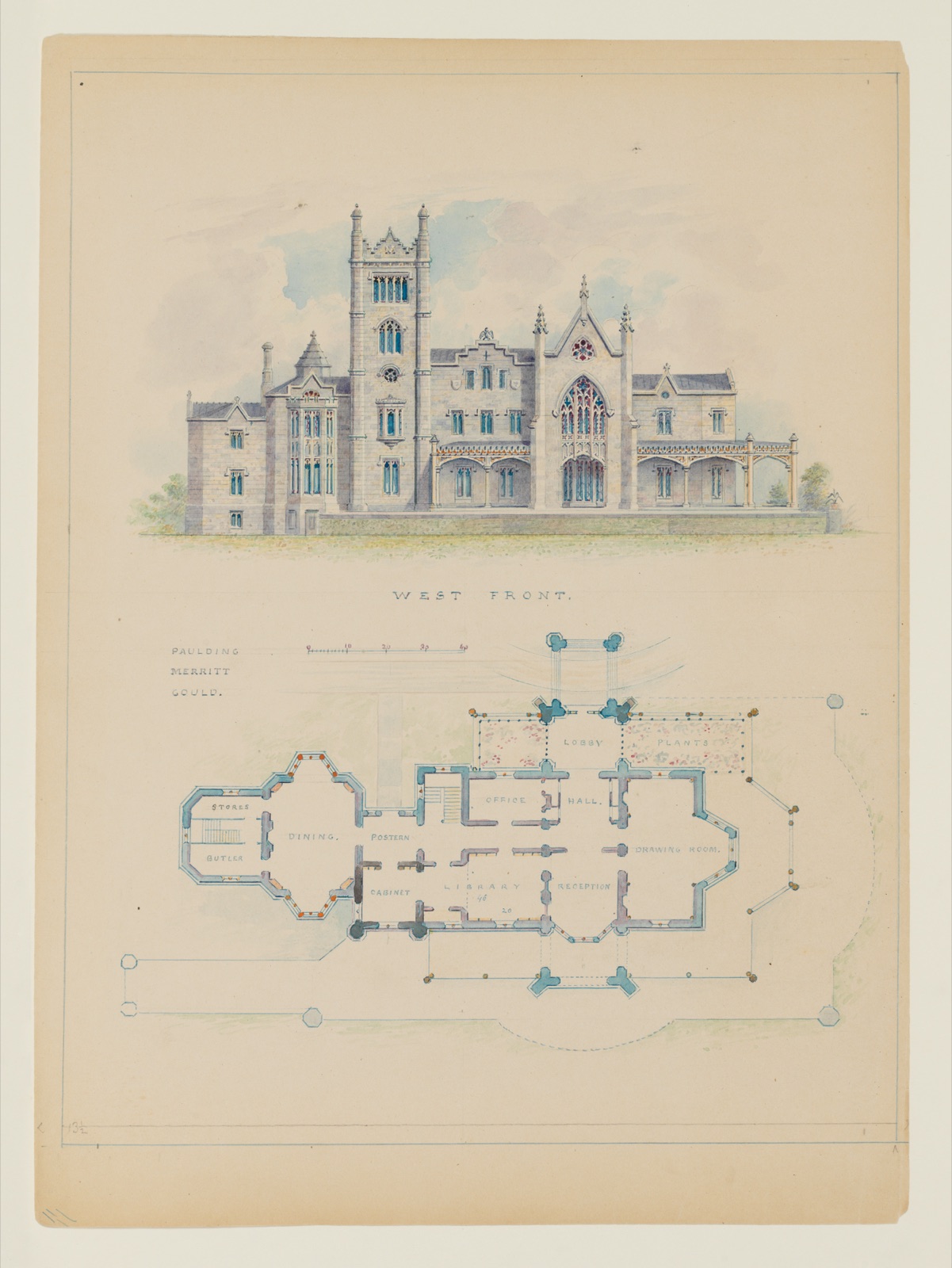

Text alternative for the diagram
Schematic phases separate earlier Lyndhurst villa/changes, Davis’s ca. 1880–92 scrapbook drawing and modern catalogue image; the boxes are date-status cues, not a detailed construction timeline.
Measured heritage elevations take the later viewpoint in another direction. The National Park Service’s HABS field guidance asks surveyors to run continuous vertical strings at corners and through openings from a shared horizontal datum. More than one datum may be needed for a tall building; a plumb bob can capture a wall that leans; brick courses are counted or measured where they tie to sills and heads; a round column is checked at intervals for entasis. For a porch that blocks the wall, the survey sketches the wall and porch separately. Published HABS conventions draw doors closed, windows as opaque and depth through line weights rather than invented shadows. Those choices aim at comparable records of the observed building at survey time. They are not evidence of what an architect originally intended, nor a prescription for Boullée’s wash. [32]
Historic England’s photogrammetry guidance approaches the same difficulty through overlapping photographs, oblique coverage and surveyed control. A rectified face can yield scalable documentation, but an invisible sill top, roof surface or area behind a projection cannot be recovered faithfully simply by smoothing an image. Supplemental measurement or a clearly signalled gap is needed. Its later geospatial guidance treats scanning and photogrammetry as methods chosen for analysis, condition and conservation needs, not as automatic substitutes for documentary history. Even a technically sharp ortho-image can record a wall as it stood after damage, repair or a new opening. [33], [34]

Text alternative for the diagram
An invented leaning face is checked against a horizontal datum; a separate invented porch hides wall that must be recorded independently. This explains HABS and Historic England survey limits.
English Heritage’s research history for Ashby de la Zouch Castle places Thomas Fosbrooke’s measured drawings of the ruins with their accompanying narrative in 1911. The castle was centuries older. The record’s worth lies in the disciplined documentation of surviving fabric, while its date and ruin condition separate it from the original builders’ intentions. Antiquarian pictures, measured later sheets and the current masonry can all be informative, but they answer different questions. [35]
Drawing survival, design history and what to compare
Archives rarely retain a perfectly matched plan, four elevations, sections, details and every revision of a project. The Uffizi study of San Firenze inventories forty-one project drawings, yet only one facade among eleven plans, twenty longitudinal sections, three transverse sections and six detail sections. Some stages survive as copies; another is lost but documented. A historian cannot fill the exterior design history by assuming those many interior or plan sheets are all simultaneous and that the single facade is the definitive built front. Unequal survival is itself a warning against overconfident reconstruction. [29]
The CCA’s House VI inventory shows a modern equivalent of documentary strata: four proposal elevation sheets sit within a project archive catalogued with 451 drawings and 339 reprographic copies, alongside later changes and renovation material. Those totals describe the project archive, not a count of elevations. A presentation front, a construction sheet and an altered-building record belong to different moments even under one project name. Their sequence can explain a design’s evolution when dates and labels are known; otherwise the most polished image may merely be the easiest to publish. [27]
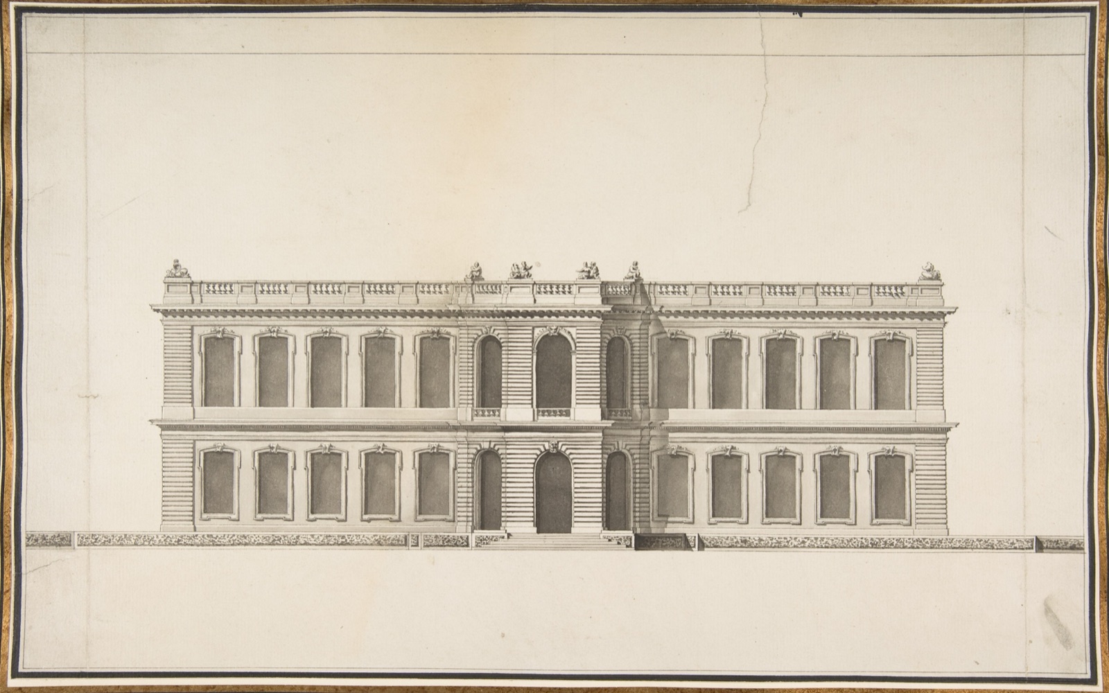
The anonymous French house elevation shown here has a long, repetitive frontage and a stronger central passage, but its Met catalogue supplies no secure architect, client or place. It can help us compare bay rhythm and central emphasis with named projects without being assigned to one of them. The sheet’s lack of attribution is not a failure to be remedied by resemblance. It is part of the object’s honest meaning. [16]
The strongest reading of an elevation begins with its particular object: face named, maker and other design hands, drawing date, medium, scale, inscriptions, repository, project phase, and whether its subject had already been built. Then compare the face with a plan for depth and site, a section for heights and assembly, other elevations for unequal treatments, and later photographs or measured records for change. A mismatch may register design choice, publication rearrangement, archive loss, renovation or survey date instead of mere drafting error. An elevation gains historical force not by pretending to be the building, but by showing how people imagined, explained, instructed and later witnessed one of its faces. [1], [11], [14], [24], [25], [27], [28], [29], [31], [32], [33], [34], [35], [36]
Explore RELATED Artworks and Records
Church, garden, university and interior elevations reveal different design questions.
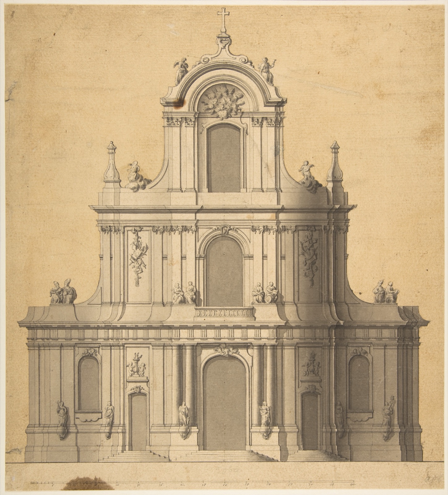
An unnamed church west front
A facade with scale, not a securely identified built church.
The Met · public-domain drawing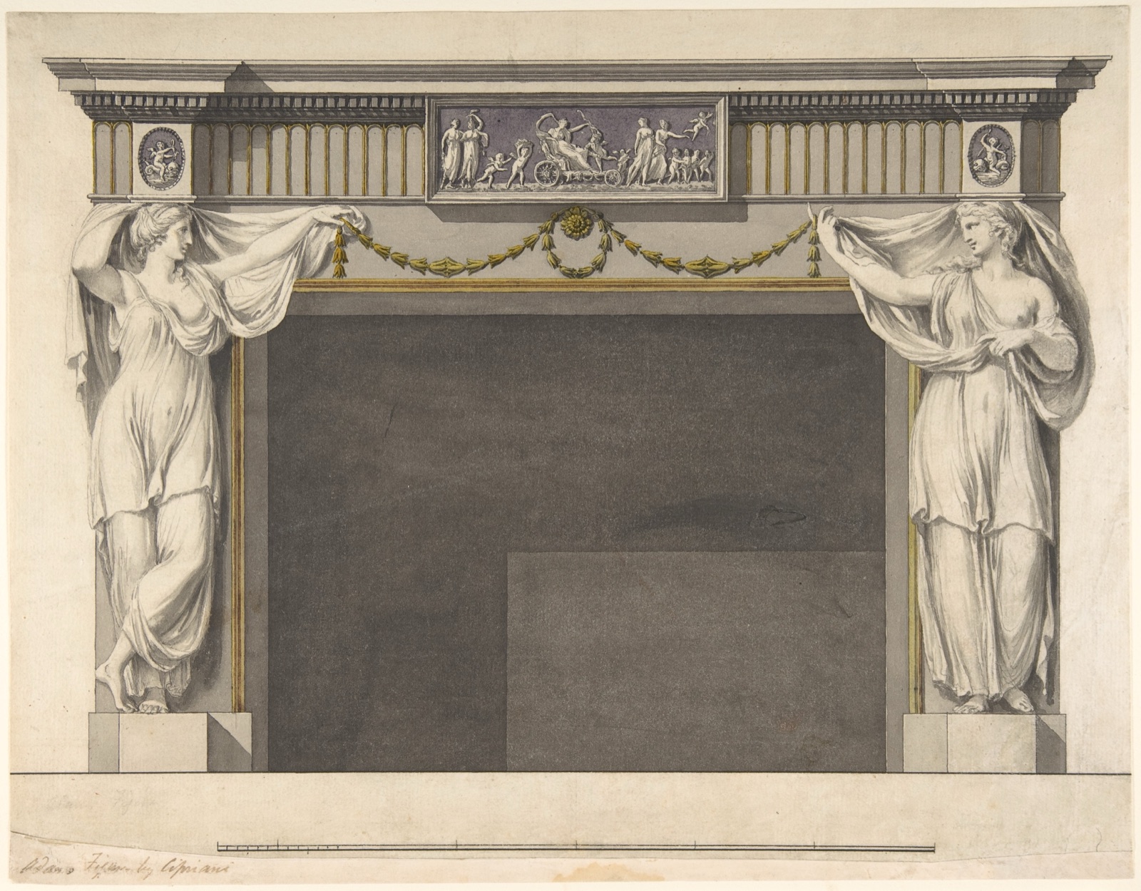
Adam’s Harewood fireplace
Interior elevation for a named estate commission.
The Met · public-domain drawing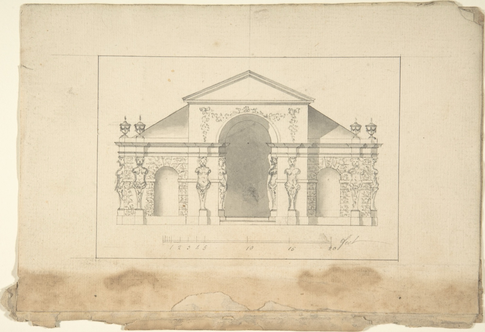
A garden pavilion front
A small-scale elevation after Robert Morris.
The Met · public-domain drawing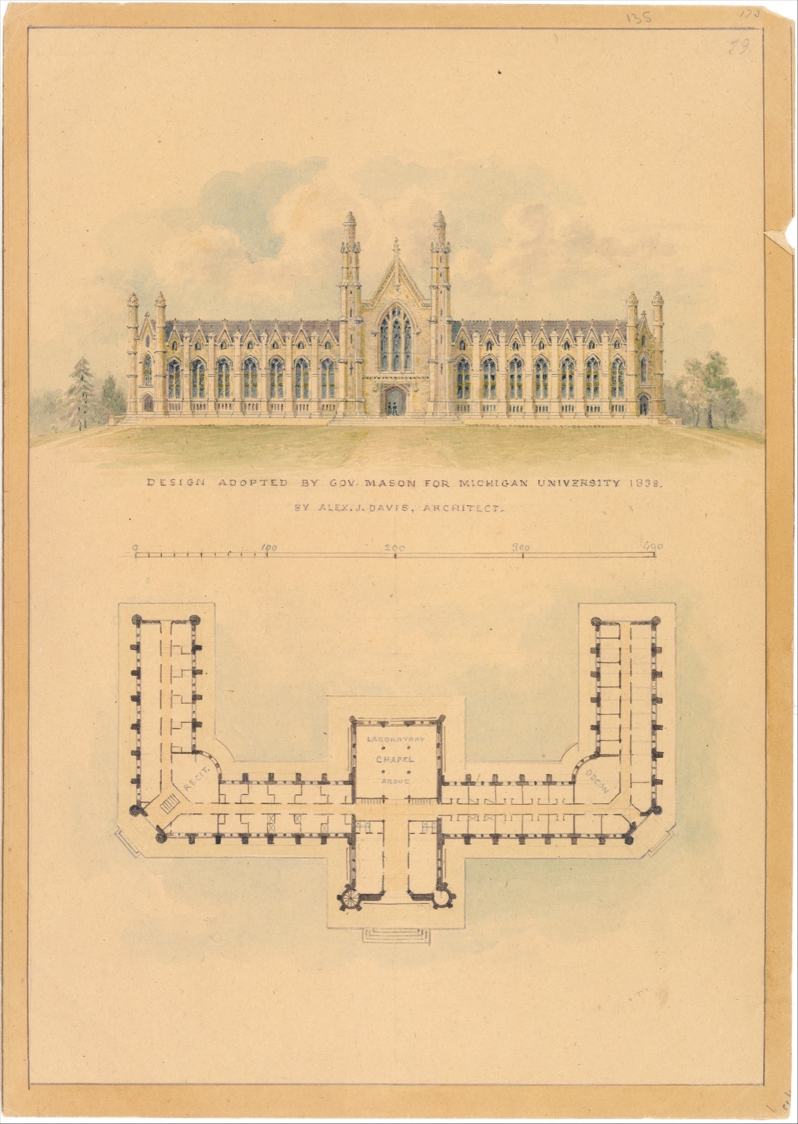
Michigan University views
Davis’s adopted proposal pairs facade and plan.
The Met · public-domain drawingWatch: Architectural Elevations
Institutional films on drawing geometry and the material life of a sheet.
Learning from Roriczer’s Pinnacle
A modern animation of historic plan-to-elevation geometry. [4]
Original illustrated preview, not a film still.
Reconstructing a Gothic Vault Design
A contemporary demonstration based on a historic Vienna drawing. [5]
Original illustrated preview, not a film still.
Conserving Michelangelo
Conservation of an architectural drawing on loan from Oxford. [6]
Original illustrated preview, not a film still.Frequently Asked Questions
No. It is a constructed frontal view whose projection, date, detail and purpose must be identified. [30] [31] [32]
They disclose projections, height relations and assemblies the front alone can conceal. [13] [28] [32]
No. A doctoral plate study found only a subset with that coupling and several other layouts. [28]
References
- Robert Branner, “A Fifteenth-Century French Architectural Drawing at The Cloisters,” Met Journal 11 (1976).
- Met, Gothic by Design exhibition galleries and objects.
- Met, Wenzel von Olmütz, Gothic pinnacle elevation and plan, 336168.
- Met, Learning from Roriczer’s Pinnacle, 2026.
- Met, Reconstructing a Gothic Vault Design, 2026.
- Met, Conserving Michelangelo, 2017.
- Met, Cigoli, facade design elevation, 334713.
- Met, anonymous Piedmontese, octagonal-cupola elevation, 365852.
- Met, Robert Adam, Croome Court greenhouse elevation, 362214.
- Met, Happe, Marché à la Volaille facade elevation, 362750.
- Met, First Merchants’ Exchange facade elevation, 339869.
- Met, Davis, Chamberlin House entrance elevation, 394186.
- Met, Davis, Lyndhurst technical oriel/window drawing, 913012.
- Met, Davis, late Lyndhurst west front and plan, 913416.
- Met, anonymous British, five-bay facade and wall plan, 363209.
- Met, anonymous French, house elevation, 351709.
- Mussolin and Speelberg, Met, “How to Read (and Display) Architectural Drawings,” 2017.
- BnF, Boullée, rue Colbert library entrance elevation, 1788.
- BnF, Boullée, Élévation non assujettie, project 9 plate 35.
- BnF, Boullée, geometric funerary-monument elevation.
- BnF, Boullée, triumphal arch “élévation perspective”.
- Politecnico di Milano, Piero Bottoni academic drawing inventory, 1921–26.
- Politecnico di Milano, Bottoni and Pucci, Parma house project, 1936–37.
- Kyoto University, Conder front and side elevations and section, RB00020115.
- Kyoto University, Conder German Embassy drawing corpus, RB00020087.
- Kyoto University, Nakai imperial-palace carpenter drawing collection.
- CCA, Peter Eisenman House VI project inventory.
- Valdivia Steel, TU Berlin, Andrea Palladio and the Disciplinary Use of Architectural Drawings, 2018.
- Uffizi, Imagines 6 (2022), San Firenze drawing study.
- Osanz Díaz et al., UPM, Spanish architecture/CAD drawing pedagogy, 2010.
- Valiente López, Martínez Borrell and Anta Fernández, UPM, Levantamiento de planos, 2006.
- NPS, HABS Guidelines: Measured Drawings.
- Historic England, Photogrammetric Applications for Cultural Heritage.
- Historic England, Surveying and Recording Heritage.
- English Heritage, Ashby de la Zouch Castle research history.
- AIA, Quality Control: Preparation of Working Drawings.
- Met, Lorenz Lechler and unidentified artist, monumental sacrament-house design, 2022.256, and Femke Speelberg’s 2022 curatorial account.
Explore RELATED Architecture
These built-place pages show why plans, perspective, photographs and later records must be read together.
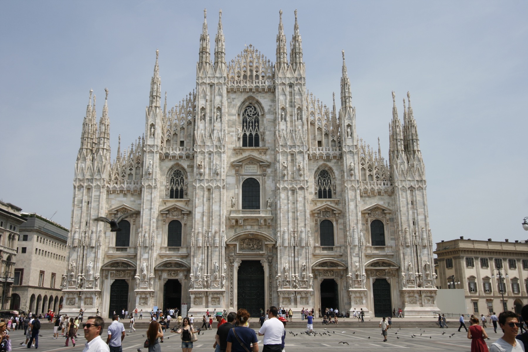
Milan Cathedral
Design and geometry changed through argument and building.
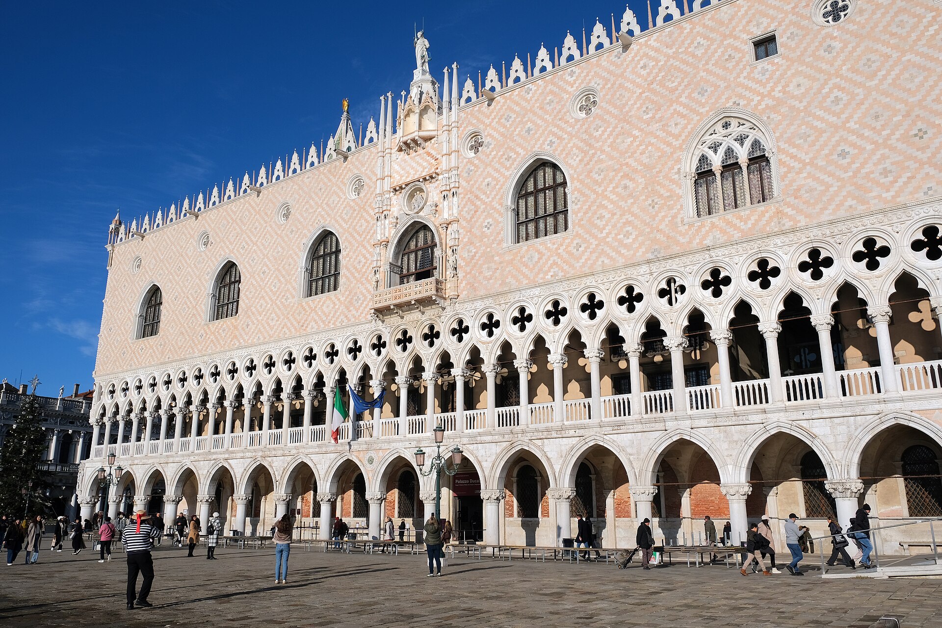
Doge's Palace
A facade conceals a long sequence of alterations and uses.
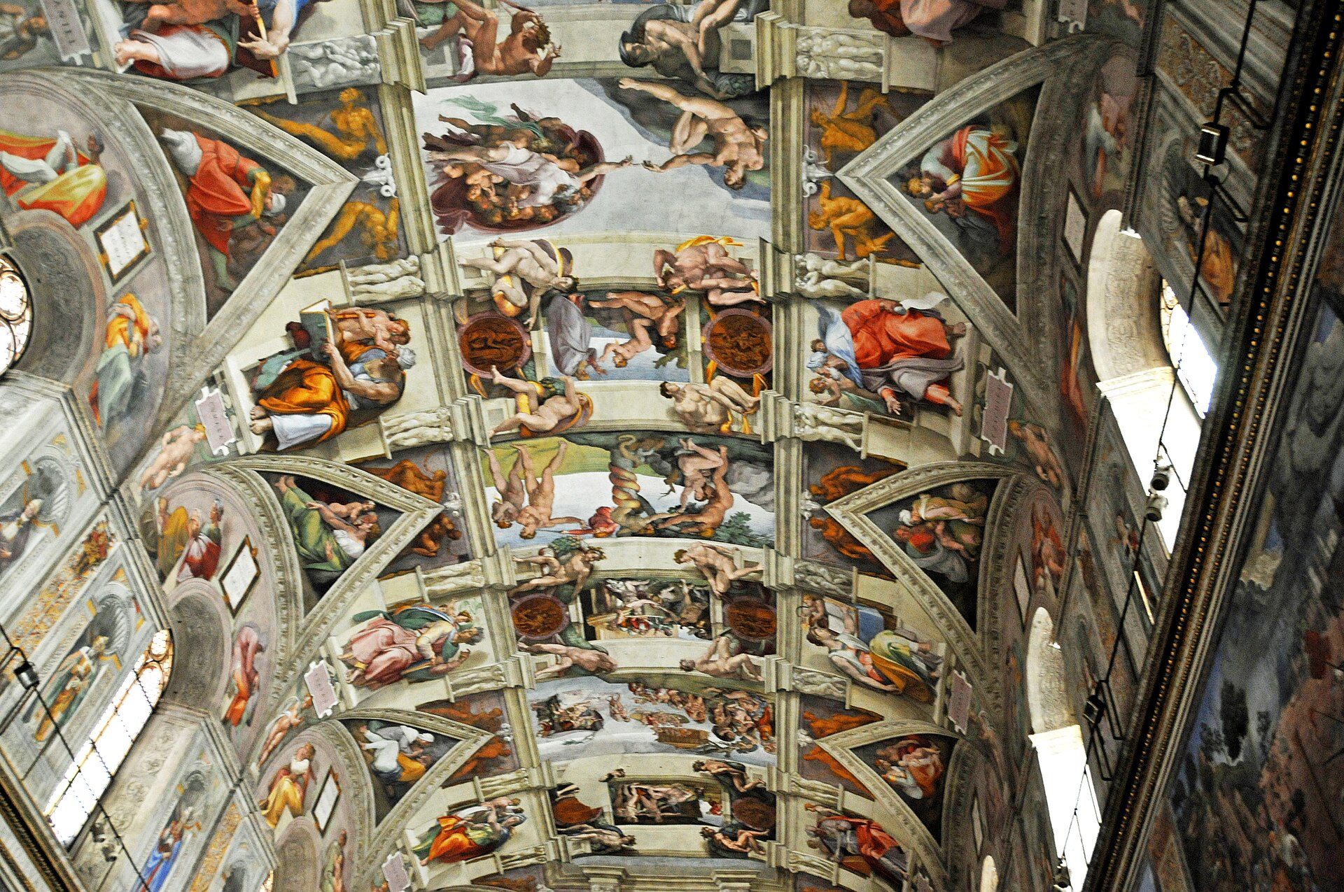
Sistine Chapel
Architectural fabric and painted programmes have different records.

Borobudur
Plan and visitor sequence reveal different spatial relations.

Machu Picchu
Ruins and later surveys mediate the reading of built terraces.
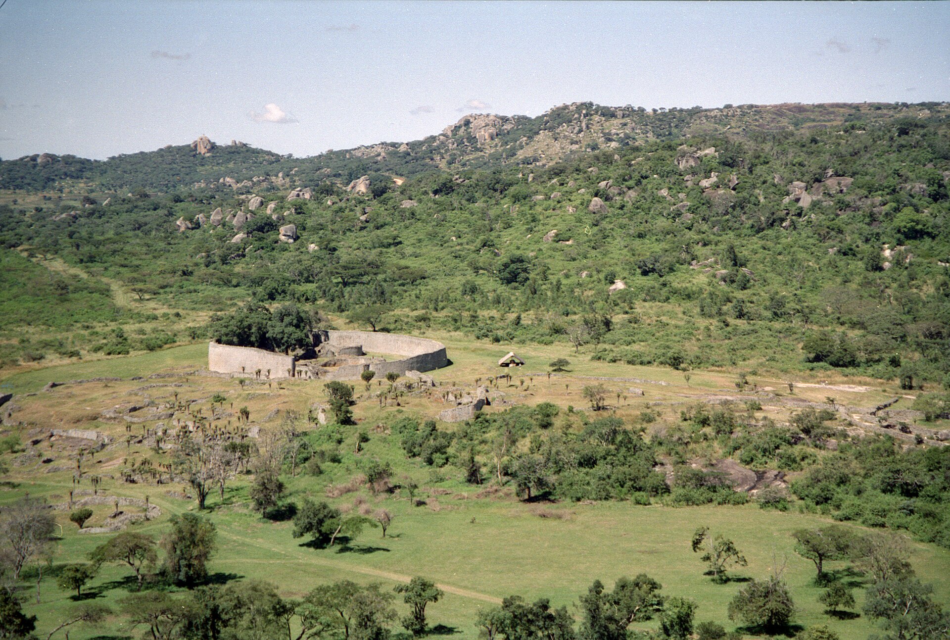
Great Zimbabwe
Heritage records must distinguish fabric from later inference.
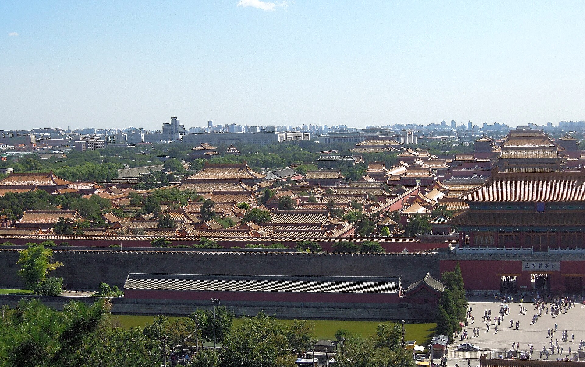
Forbidden City
Palace plans and surviving courts changed across reigns.

Teotihuacan
Archaeological plan and exposed monuments are not the whole city.