


 by Tom Gurney
Tom Gurney BSc (Hons) is an art history expert with over 20 years experience
Email: tomgurney1@gmail.com / Phone: +44 7429 011000
Viewpoint, Design Argument and Record
A perspective drawing offers a building to an imagined viewer. Receding lines and diminishing sizes bring a room, street or proposed façade into something like the experience of looking through a window. A person can instantly sense a ceiling's height, a stair's invitation or a tower's dominance, although the paper is flat. This immediacy has made perspective invaluable in architectural design, presentation, publishing and teaching. It also makes the drawing persuasive. A viewpoint can favour one entrance, suppress a service wing, enlarge a hall or set a building against a landscape that has yet to exist. The apparent realism of a perspective is therefore both its gift and its danger. It does not by itself give the true length of a wall, the angle of a junction, construction detail or independent proof that a proposal was built. [1], [2], [3], [13], [25]
Architects have not always given perspectival views the same job. Renaissance books formalised central projection, but architects also used plans, elevations and sections whose distances could be compared more directly. An eighteenth-century stage designer could draw an impossible arcaded city to move an audience; a topographical artist could record a palace from its lawn; a nineteenth-century architect could wash a church proposal to impress a patron. German architect Heinrich Tessenow later used perspectives in journals and books to reason about ordinary houses, rooms and things, while Cedric Price and Paul Rudolph combined viewpoints with diagrams or cuts to explore new kinds of building. Edo Japanese urban prints show another use of converging streets: the eye can be led towards a landmark rather than asked to believe in a mathematically uniform illusion. The history of perspective drawing is not a march from inaccurate art to accurate technology; it is a history of particular visual choices serving particular architectural arguments. [7], [8], [13], [14], [15], [16], [17], [18], [19], [20], [21], [22], [23], [24], [27], [28], [29], [30], [31], [32], [33]
At a Glance
- Core ideaA selected viewpoint projects three-dimensional space onto a flat picture plane. [1], [2], [3]
- Vanishing pointA family of parallel directions in space tends towards a point in a central projection; different directions have different points. [1], [2]
- HorizonFor directions parallel to a level ground plane, their vanishing points lie on its eye-level horizon line. [1], [2], [3]
- One, two or threeThese labels describe the visible convergence of a rectilinear subject's main axes, not a hierarchy of artistic merit. [1]
- What it shows wellApproach, atmosphere, light, material, people and several spatial relationships in one chosen view. [7], [13], [27], [28], [29], [30], [31], [32], [33]
- What it cannot give aloneTrue wall lengths, angles, depth, hidden construction or executed status. [2], [20], [25], [26]
- Read its statusDistinguish survey view, preliminary sketch, competition presentation, scenic illusion and printed capriccio. [9], [12], [20], [27], [28], [29], [30], [31], [32], [33]
- Read with other recordsPlans, sections, elevations, models, photographs and dated archives test the persuasive single view. [8], [14], [17], [18], [25], [26], [32]
Contents
- A viewer, a plane and a family of receding lines
- One-point, two-point and the deliberately adjusted vertical
- Renaissance reports, Alberti's window and Serlio's printed lesson
- Why orthographic drawings remained essential
- Wash, proposal and the public viewer
- Stage space, diagonal vista and painted architecture
- Perspectives that think: ordinary houses and changed publication context
- Hybrid cuts, changing houses and urban viewpoint
- Edo streets and other spatial languages
- What a perspective can prove, and what it cannot
A viewer, a plane and a family of receding lines
The geometry begins with a viewer's position and a surface on which points in space are projected. In a drawing this surface is the picture plane. Imagine a pane of glass held in front of the viewer: each visible point would be placed where the line from that point to the viewer crosses the glass. The relation is central rather than parallel projection because the sightlines converge at the viewer. Changing the viewer's station or the plane changes the image without moving the building. A low station can make a portico monumental; a high one can reveal a roof, garden or urban plan. [1], [2], [3]

Text alternative for the diagram
An invented eye at left sends three red rays through a gold picture-plane line toward three drawn building points; moving the eye alters the image.
A vanishing point is not a magical dot into which all lines in a drawing disappear. It belongs to a family of lines sharing one direction in three-dimensional space. A second direction has a second vanishing point. As MIT's explanation of pinhole image formation makes clear, the projected position of an infinitely distant line depends on its direction, not on the line's original position. Straight lines and incidence—the meeting of a point with a line—are preserved by this projection. Angles, lengths, parallelism on the page and depth are generally not. Thus two equal bays can appear unequal in a perspective because one is farther away. A true dimension must come from measurements, a known geometry, another drawing or a carefully calibrated image rather than from the bay's apparent width alone. [2]
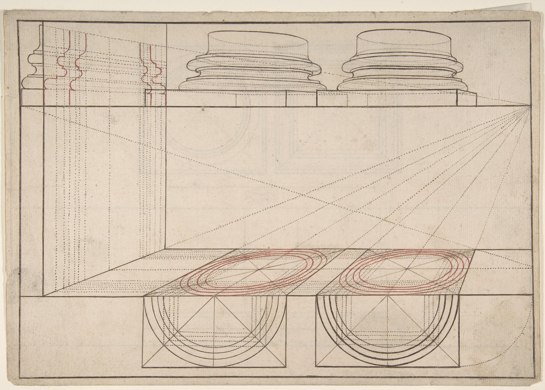
The horizon line has a narrower technical meaning than a drawn mountain edge or boundary between sky and land. For a level ground plane, horizontal directions on that plane have vanishing points on a line corresponding to the viewer's eye level. If the viewer looks down from a tower, the ground horizon can fall high in the picture; if the viewer crouches, it sits lower. The Art Institute of Chicago's construction primer uses orthogonals and a separate distance point to lay out a tiled floor. The purpose is to keep equal ground intervals coherent even as they shrink visually. A spectacular vista may omit every construction mark, but a study sheet can retain them beneath wash or ink, showing where the apparently effortless spatial effect came from. [1], [3]
An anonymous seventeenth-century Italian architectural exercise at the Met is small and exact about its chosen subject: two column bases appear on the recto with ruled pen construction, while a column capital and a measurement key occupy the verso. It is not a grand palace. It shows that perspectival skill could be learned at the scale of a single architectural member, with ruler and measurement part of the same sheet. A vanishing system could help describe how a base turns in space, but the verso key—not the projected width of the nearer torus—carries the measurable information. The drawing belongs in a history of architectural work as well as one of illusion. [31]
One-point, two-point and the deliberately adjusted vertical
The familiar one-, two- and three-point labels arise most clearly when a rectilinear box is turned relative to a viewer. Face a box squarely at eye level and the lines running away converge towards one principal point while the front edges stay parallel to the paper. Turn to its corner at eye level and two horizontal families converge towards different points, leaving vertical edges parallel. Aim steeply upward or downward and the vertical family can converge too. The categories describe orientation between subject and viewer; they do not say that three points are more truthful or that one point is elementary art. Buildings with curved walls or irregular axes may have directions that do not fit a tidy three-family illustration. [1]

Text alternative for the diagram
Three invented boxes marked 1, 2 and 3 points distinguish different orientations, not degrees of architectural accuracy.
In practice an architect may straighten verticals even when the imagined viewer is looking slightly upward. Columbia GSAPP's projection lesson calls this a forced two-point view in a digital context: the resulting verticals stay upright on the page while the building remains corner-on. It can keep a tall tower from seeming to topple inward, but it modifies the strict projection. A nineteenth-century watercolor labelled perspective elevation may similarly blend the broad frontal legibility of an elevation with enough depth to reveal a side face. The label tells us the image's hybrid purpose, not that every line belongs to a single mathematically exact camera. [1], [33]
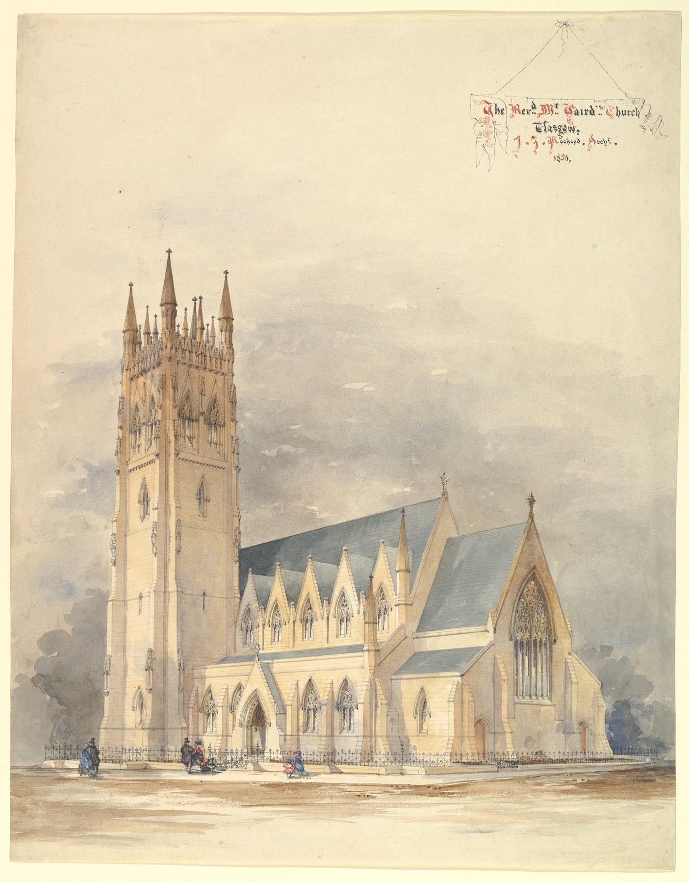
Designed by J. T. Rochead, the Met's 1858 Perspective Elevation of Reverend Mr. Gaird's Church, Glasgow, in the Gothic Style uses watercolor and ink to present a proposed Gothic church. Its towers, openings and side depth could give a patron or committee a more immediate sense of mass than a flat front would. Yet the object record identifies a design sheet, not an independent survey of a completed church. This distinction matters precisely because the drawing appears convincing. The viewer can judge the architect's intended composition and its chosen approach, but a dated visit, building record or photograph would be required to establish what stood on the Glasgow site. [33]
A perspective's field of view is another choice. A wide viewing angle takes in more of a room from the same station but makes near edges and oblique sides more dramatic; a narrower view can compress an arrangement into a calmer-looking picture. In a historic drawing there may be no camera specification, but the basic effect still matters when reading an unusually elongated hall or towering foreground. The precise question is not whether the perspective 'looks real'; it is what station, framing, line adjustment and visual emphasis were used to make this building legible to its intended reader. [1], [2]
Renaissance reports, Alberti's window and Serlio's printed lesson
Accounts of European linear perspective often begin with Filippo Brunelleschi's reported demonstration using a panel of the Florentine Baptistery and a mirror. The original panels do not survive. The story describes a striking way to compare a painted view with the seen building, not an experiment whose exact optical precision can now be retested from the lost object. Earlier cultures and periods had multiple ways to represent spatial depth, and the Florentine achievement should not be turned into a claim that no one had imagined space before about 1415. Its historical significance lies in a formally described central projection and the new visual possibilities this opened for art and architecture. [4], [7], [21], [24]
Leon Battista Alberti's treatise De pictura, written in 1435, described a system for painting the visible world through a framed surface. A picture can be thought of as a window onto a scene, with geometric relations giving architecture, figures and floor patterns a coherent apparent depth. Alberti also wrote De re aedificatoria on architecture, but the discussion of pictorial linear perspective belongs to the painting treatise. The distinction is worth keeping: techniques of image-making could circulate among painters and architects without making a perspective picture itself a complete set of building instructions. [4]

Text alternative for the diagram
An invented floor starts at the bottom edge; teal rays converge at a red point on an eye-level gold horizon while red cross-lines compress toward it.
Sebastiano Serlio made such methods public in a different form. His first book concerns geometry and his second is explicitly on perspettiva. The Bibliothèque nationale de France records the Italian–French Paris edition printed by Jean Barbé on 22 August 1545, with Jean Martin's French translation and 132 woodcuts. A Met copy also catalogues 1545 and identifies the translator. These details matter more than a vague statement that Renaissance theory 'spread': bilingual vernacular pages and repeatable printed figures could make perspective legible to a much larger readership, and the book was an architectural as well as pictorial publication. The stage scenes and demonstrated spaces belong to this culture of printed instruction, even though the page could not make every reader a competent perspectivist by itself. [5], [6]
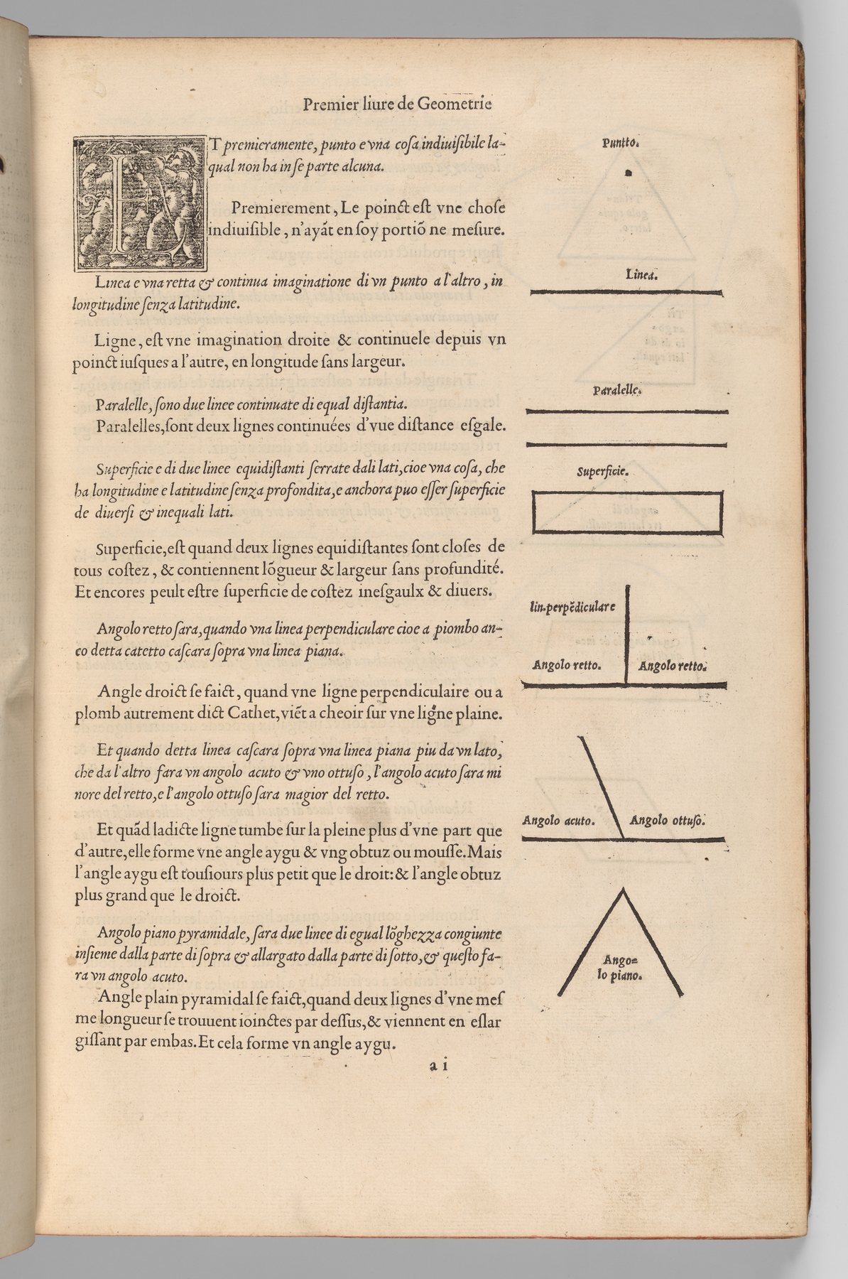
The printed object offers a caution about visual authority. A woodcut showing a pavement or colonnade is an exercise in how to organise recession, not automatically a survey of a place that existed. Serlio's edition was published after the Florentine discussions, in a transnational Italian–French setting. The dates should not be compressed into a single 'invention'. Nor should every perspective be attributed to a Renaissance painter: architectural printers, translators, patrons and stage technicians helped decide which geometric devices became useful public visual language. [4], [5], [6]
The Canadian Centre for Architecture catalogues a later printed perspectival view of Michelangelo's Campidoglio scheme in Rome, etched by Étienne Du Pérac and issued by Antoine Lafréry in 1569. It is simultaneously associated with design and record, and its bird's-eye view mediates a famous urban project for readers who need not stand in the piazza. But the etcher's dated print is not an autograph design drawing by Michelangelo. To compare a drawn city with its later built form, one must keep maker, publisher, date and design phase apart. Perspective can transmit architecture across distance while also adding another interpretive hand. [9]
Why orthographic drawings remained essential
Perspectival realism never displaced the measured promise of all other architectural views. A plan locates rooms and routes in the horizontal plane; an elevation faces a wall directly; a section opens floors, vaults and hidden relations in a selected cut. Because these views generally use parallel projection, a consistent drawing scale can align dimensions along their relevant plane more readily than a perspectival picture can. A perspective can let a client sense what it might be like to enter a chamber; a plan can tell a builder which walls enclose it; a section can tell both how its ceiling sits below a roof. They are complementary claims, not rival versions of one single truth. [1], [2], [8], [25]

Text alternative for the diagram
Two invented frames contrast parallel teal vertical members at left with red convergent members at right; neither provides a historic building measurement.
The original RIBA catalogue of Antonio Visentini's eighteenth-century drawing workshop makes this coexistence historically tangible. Its introduction distinguishes vedute—picturesque or topographical views—from sheets of individual buildings made in strict orthographic projection. Visentini's atelier supplied a market for renderings of Venetian monuments, but it also produced a large corpus of flat building records and copies. The catalogue says Daniele Barbaro regarded perspective as less accurate than orthographic projection for architecture, while carefully leaving open whether that preference influenced Palladio or reflected a shared milieu. It says that, so far as we know, Palladio did not use perspective to record old buildings or invent new ones, and that plans and direct elevations suited his ratios and reconstructions. This is a claim about a principal project method and surviving corpus, not that Palladio never drew a perspective line: another RIBA collection story displays a cornice perspective exercise. [7], [8]
Visentini's case also prevents a false moral distinction between 'objective' orthographic drawing and 'subjective' perspectival view. A flat measured-looking sheet can copy an earlier book, restore a ruin hypothetically, suppress damage or reorganise an ancient fragment into an ideal whole. A veduta can be made from observation and still move a viewpoint for effect. Both need dates, purposes and source histories. The useful question is which relationships each method preserves and what the particular maker wanted the image to do. [2], [8]
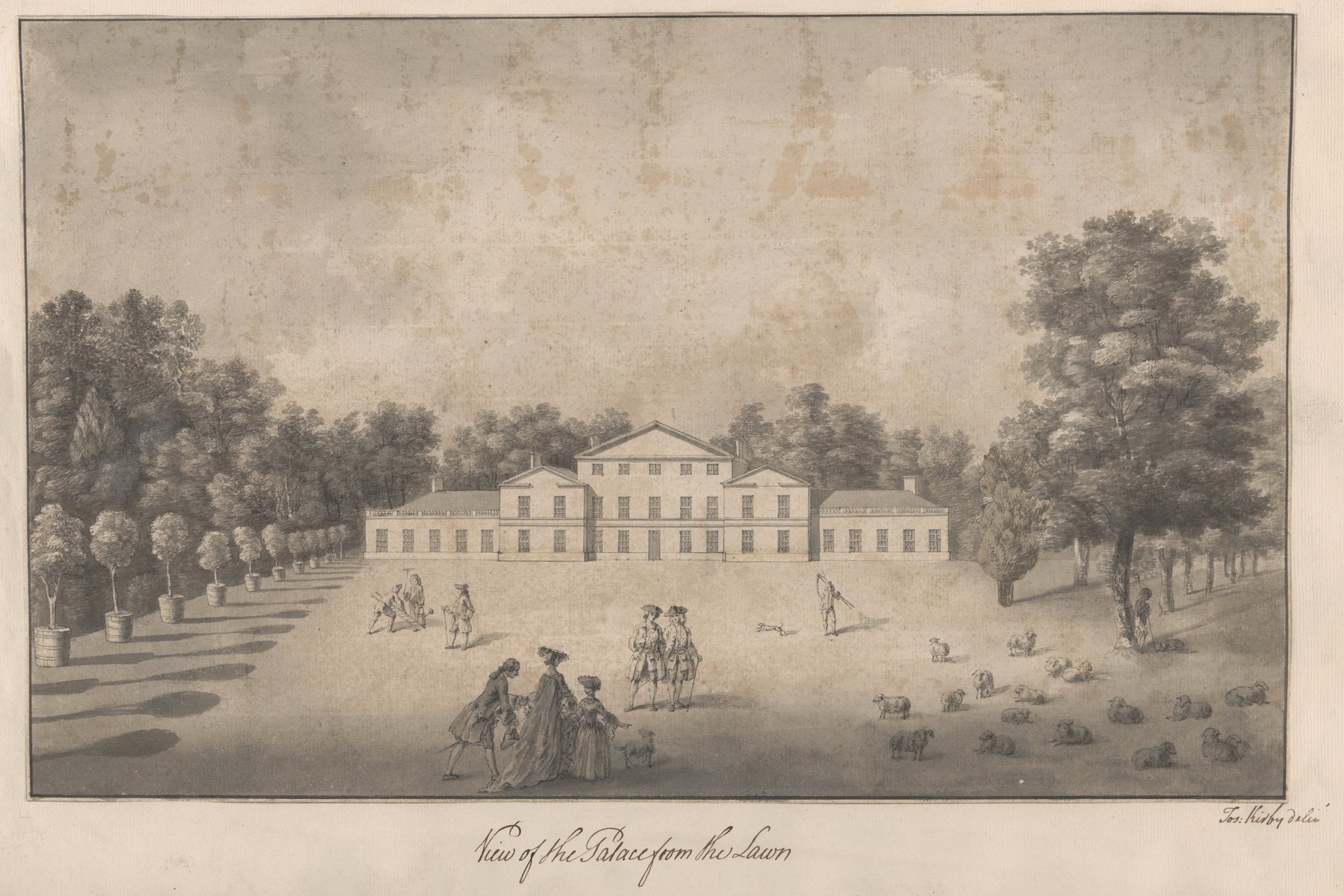
Joshua Kirby's 1763 View of the Palace from the Lawn at Kew appears in William Chambers's album explicitly bringing together plans, elevations, sections and perspective views of the gardens and buildings. The Met credits Kirby as artist and Chambers as architect. The picture's lawn station helps connect a façade with its approach and planting, while other leaves would be needed for the palace's dimensions or structural sequence. Its presence in a mixed-view album demonstrates an architectural culture not choosing one projection over all others but placing visual experience beside plan and cut. [32]
Wash, proposal and the public viewer
A finished perspective can make an unrealised scheme feel inevitable. The Bibliothèque nationale de France describes Étienne-Louis Boullée's vast Cirque sheet as an élévation perspective for a first project, dated between 1781 and 1793. In ink and coloured wash, at about 148 by 58 centimetres, the design gathers a colonnaded outer wall, three auditorium tiers and two Trajan-like columns into a statement of public grandeur. The sheet's scale and finish made it a serious imaginative object. They do not establish that the proposed cirque was built. A perspective elevation can simultaneously describe an intended architecture and stage the response it wants from its audience. [12]
RIBA's perspective exhibition puts Boullée's cathedral vision beside intimate and extravagant twentieth-century proposals. Its interpretation notices how the axial view, darkness, light and scale try to overwhelm the viewer within the paper's finite size. A person drawn tiny against a vast arch does not merely supply a unit of measure; the contrast makes a claim about the building's place in civic life. For a history of an unbuilt project, that visual rhetoric is essential evidence of ambition, even if engineering feasibility must be judged from sections, spans, materials and other records rather than from the shaded vista alone. [7], [12]

Text alternative for the diagram
Two invented frames place a gold eye low and high beside a portico outline; one draws attention to approach, the other to roof/site.
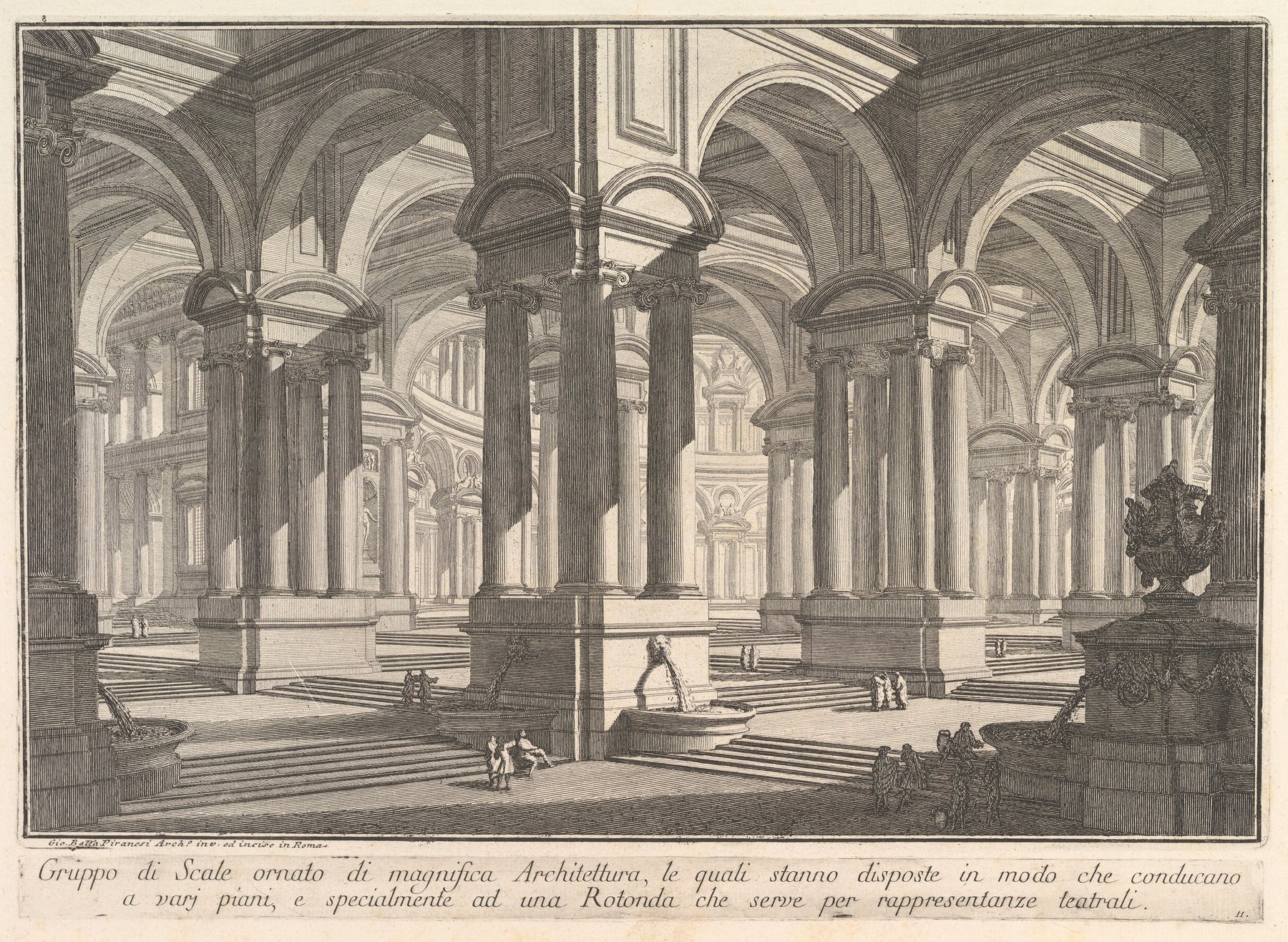
Piranesi's etching Stairways adorned by magnificent architecture, from his Prima Parte di Architettura, e Prospettive and dated by the Met to around 1750, extends the point. Stairs, arches and architectural members pile up into an invented spatial experience. The image may borrow ancient vocabulary, but its dramatic circulation is a capriccio and printmaker's proposition, not a photograph-like account of an excavated building. Its recession asks the viewer to inhabit an imaginative architecture. Treating such an image as a false survey would miss what it was for; treating it as context-free decoration would miss its argument about architectural possibility. [27]
An explicitly unexecuted example appears much later in the Canadian Centre for Architecture. Ross & Macdonald's preliminary exterior perspective for proposed CBC studios and a medical building in Toronto carries the exact date 3 June 1938 and labels its office/communications scheme unexecuted. The catalogue identifies a reprographic copy, not necessarily the one original master sheet. The exterior view could convey a projected civic presence, while its title and archival status prevent the viewer from reading it as a record of Toronto's built street. Comparing that image with later photographs requires first locating whether a different design or any building appeared at the site at all. [20]
The Met's nineteenth-century Glasgow church drawing presents a parallel caution: architectural watercolour was an argument that could win a commission, explain an intention or circulate in a catalogue. Maker and sheet date are known, while executed status is not. The same visual polish that makes a proposal readable must make a historian ask what phase of the project the image belongs to. [33]
Stage space, diagonal vista and painted architecture
Theatre design gives perspective an unusual architectural job. A built auditorium may be shallow, yet painted wings, receding streets and controlled sightlines can make a spectator believe in a much deeper scene. This illusion is not a failed building survey: it is part of the theatre's designed performance. The Bibiena family moved away from a single square-on vanishing point towards angled views and multiple directional points, allowing a stage city or palace to open away from the obvious central axis. RIBA's collection-based history notes the imaginative depth this created in small stage drawings. One must still distinguish a painted scenic proposal from the joinery, rigging or backstage plan that would let it be performed. [7], [28], [29]
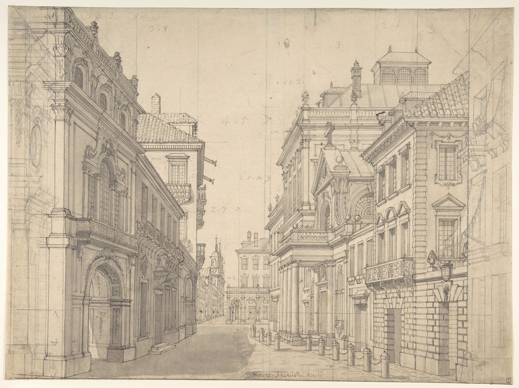
Antonio Mauro II's Met sheet, Perspective Design for a Stage Set of an Italian Cityscape, is particularly instructive because construction and finish coexist. The museum dates it broadly to 1784–97 and names pen and ink, brown and grey washes, and leadpoint vertical lines used for the architectural construction. A spectator-facing imagined street is built up from drawing marks that remained visible on the physical sheet. The fine guide lines do not prove the stage was realised; they show the work of making convincing recession. If the resulting painted façades contradict real masonry or streets, their purpose was still intelligible: to direct a seated audience into an imagined distance. [28]
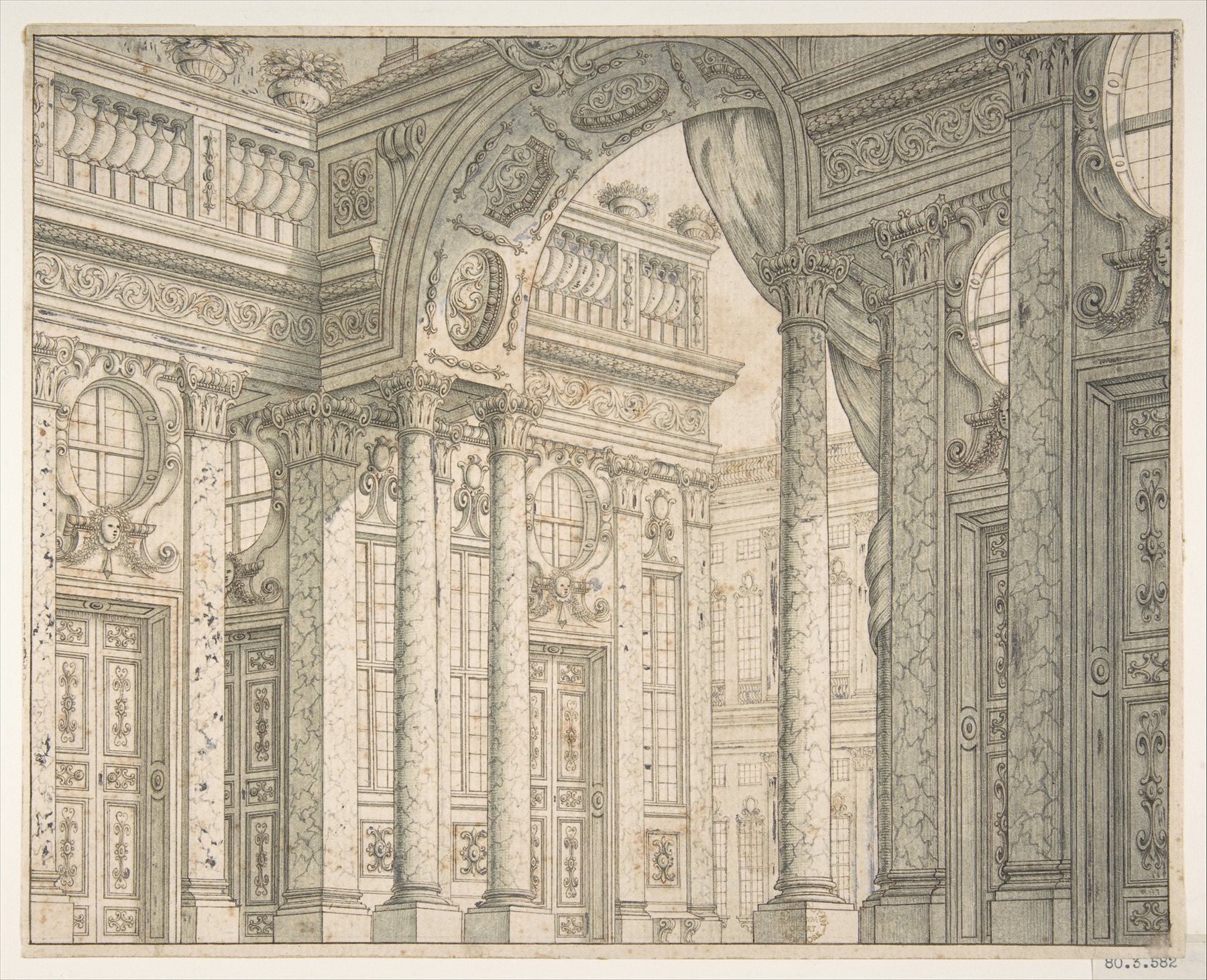
The Met's stage courtyard and triumphal arch is attributed to the circle of Ferdinando Galli Bibiena, not securely to his hand. Its pen, green and grey wash over leadpoint suggest another progression from scaffolding lines to rendered ceremonial setting. The unusual diagonal viewpoint can place an arch beyond a foreground court, creating the sense that spectacle continues outside the paper. The catalogue's broad 1677–1743 dating and qualified attribution must remain with the image. A family-name style should not silently become autograph certainty, and a plausible stage design should not turn into a claim about one documented production. [29]
The perspective can also be built into the walls of a real room. In the Italian-language account of the Uffizi's Sala dell'Udienza pubblica in the Medici summer apartment, Angelo Michele Colonna and Agostino Mitelli paint stairs, balustrades, boxes and balconies that seem to break through the actual wall. Court figures occupy this illusionistic architecture; the room appears enlarged to someone received in audience. The patron's aim to astonish visitors makes the image political as well as spatial. Here the perspective is not a view of a proposed building but a false architecture designed within an existing one. The history must keep the real wall, painted extension and viewer's intended position separate. [11]

Text alternative for the diagram
A heavy black invented real wall separates teal real-room lines from red painted perspective rays, showing illusion rather than added masonry.
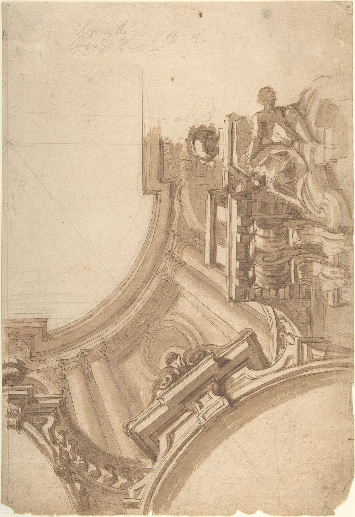
Andrea Pozzo's Perspectiva pictorum et architectorum describes such effects through Latin and Italian instructions and engraved sequences of increasingly complex architecture. The Met notes an important bibliographic complication: a copy with a 1693 title page may contain later states or even a composite assembly, and its false-dome plate does not belong to the first edition. The visual theory is real, but an edition date printed at the front cannot automatically date every leaf. A ceiling drawing at the Met, with ruled and compass construction on one side of the sheet, similarly shows that painted architecture needed planning. A corner or dome meant to soar overhead began as marks adjusted to a viewpoint and a surface. [10], [30]
Perspectives that think: ordinary houses and changed publication context
The architectural perspective need not end in a patron-facing rendering. Heinrich Tessenow's views of houses, rooms and furniture around 1901–26 show drawing as a way of testing what ordinary dwelling could mean. Jurjen Zeinstra's TU Delft dissertation investigates not just the appearance of these images but where they first appeared and how they were later gathered into books. Early perspectives circulated in German building journals, sometimes as responses to readers' design questions; related drawings then reappeared in Tessenow's own publications. The same image changed function when detached from a practical prompt and placed within an architect's organised argument about modest domestic life. [13]
Zeinstra groups the perspectives into Haus (house), Raum (room or space) and Sache (thing or object), bringing to them three German concepts: Empfindung (sensibility), Abstraktion (abstraction) and Gewöhnlichkeit (ordinariness). This is the dissertation's analytical framework, not a three-column doctrine formally announced by Tessenow for every project. The point is that a drawing of a chair or threshold can carry a spatial idea as surely as a grand urban vista can. A door, an arbor or a room's bounds becomes an architectural question of relation, scale and use. [13]
One comparison in the dissertation makes the perspectival choice visible. Tessenow's 1905 forest grave gate is almost absorbed into densely drawn trees; the entrance is a small threshold in an open, atmospheric field. A 1926 Dresden exhibition courtyard instead presses beams, columns, paving and façade elements into a strict Cartesian grid. These two drawings do not merely choose different quantities of vanishing points. One asks how a boundary and gate feel within an enveloping landscape; the other makes order and enclosure palpable. The dissertation's plate juxtaposition prevents either image from being mistaken for a generic 'realistic perspective'. What they disclose is an architect's thinking about how built elements condition perception. [13]
RIBA's Anthony Cox student portfolio offers a different institutional setting. Its interior perspectives and sketchbook belong to the Architectural Association debates that produced the 1937 'Yellow Book' campaign for curricular reform. A finished student's interior view can demonstrate skill, but it also belongs to a teaching culture deciding what architects should learn and how freehand vision should sit beside technical requirements. The Canadian Centre for Architecture lists Cedric Price's Cambridge student projects from the early 1950s with plans, elevations, interior and exterior perspectives and, in one infants' playroom project, a cut-and-assemble model. The portfolio was not just a sequence of progressively prettier pictures. Different media could check how a small social space would look, organise and physically occupy the world. [14], [15]
Hybrid cuts, changing houses and urban viewpoint
A perspectival section opens a building while retaining a selected viewing station. It can make several floors, stairs and rooms seem to inhabit one connected volume; it cannot be read with the constant scale of an orthographic section. The Met's interview on Paul Rudolph identifies his Yale Art and Architecture Building drawings and later projects as examples of cutaway perspectives in which texture and light help communicate spatial relations. The Yale building's drawing and the building itself are related but not interchangeable evidence. A vivid cutaway can make a complex interior understandable to an audience, whereas a construction cut and detail must settle exact floor junctions, loads and routes. [16]

Text alternative for the diagram
Two invented cut-room frames align floor heights in the teal section and draw receding red floor lines in the cutaway.
At PREVI Lima, the Canadian Centre for Architecture catalogues James Stirling and Michael Wilford competition sheets for experimental low-cost housing. Their 1969 presentation material includes sectional perspectives for a neighbourhood and for houses at different stages of expansion, alongside plans, sectioned obliques and diagrams. Here a perspective does not have to pretend that one image is the final, timeless house: it can depict growth and occupant change. A view of an expanded cluster can make the proposal's social and spatial consequences legible while other drawings define the modules from which that cluster might be made. The original archive's project and stage labels matter because the image of a possible later condition is not a photograph of that future having occurred. [18]
Cedric Price's Potteries Thinkbelt records likewise put perspective sketches next to plans, sections and axonometrics of transfer areas and housing. A perspective of an arriving train or transfer structure can foreground movement and encounters; the plan maps circulation; the section tests vertical separation; an axonometric keeps components in a parallel spatial order. Price's archive describes design-development and publication sheets, which should not all be conflated as one final scheme. The decision to use several views can be itself evidence that a project was about change, assembly and activity rather than a single photogenic object. [17]
The aerial view is especially powerful—and especially liable to hide its politics—at urban scale. The CCA catalogues Arata Isozaki's signed 1962 bird's-eye perspective for the Marunouchi City in the Air proposal in Tokyo as a design-development drawing. An elevated eye can grasp urban form and relationship across blocks, but it also removes the street-level body and the differences between inhabitants. The project was a proposal, not a record of a Tokyo district that was built as drawn. Aerial perspective can make an imagined city coherent precisely by placing the viewer at a station inaccessible to ordinary pedestrians. That should be part of interpreting, rather than dismissing, the image. [19]

Text alternative for the diagram
An invented street frame has converging teal route lines; an aerial frame has red blocks seen from above. Neither describes a real city.
Edo streets and other spatial languages
European central projection is one historically influential system, not a universal test that all architecture pictures must pass. Japanese scholar Takashina's Kyoto University study examines Edo urban imagery in which painters could use western-derived one-point devices, parallel recession, or combinations. In views connected to Hokusai's Thirty-six Views of Mount Fuji, a converging street can guide the eye toward Mount Fuji or a civic landmark. The vanishing area is not just an empty abstract point: a culturally significant subject may be placed around it. The drawing's compositional goal can therefore be different from the tightly measured illusion of a Renaissance tiled floor. [21]
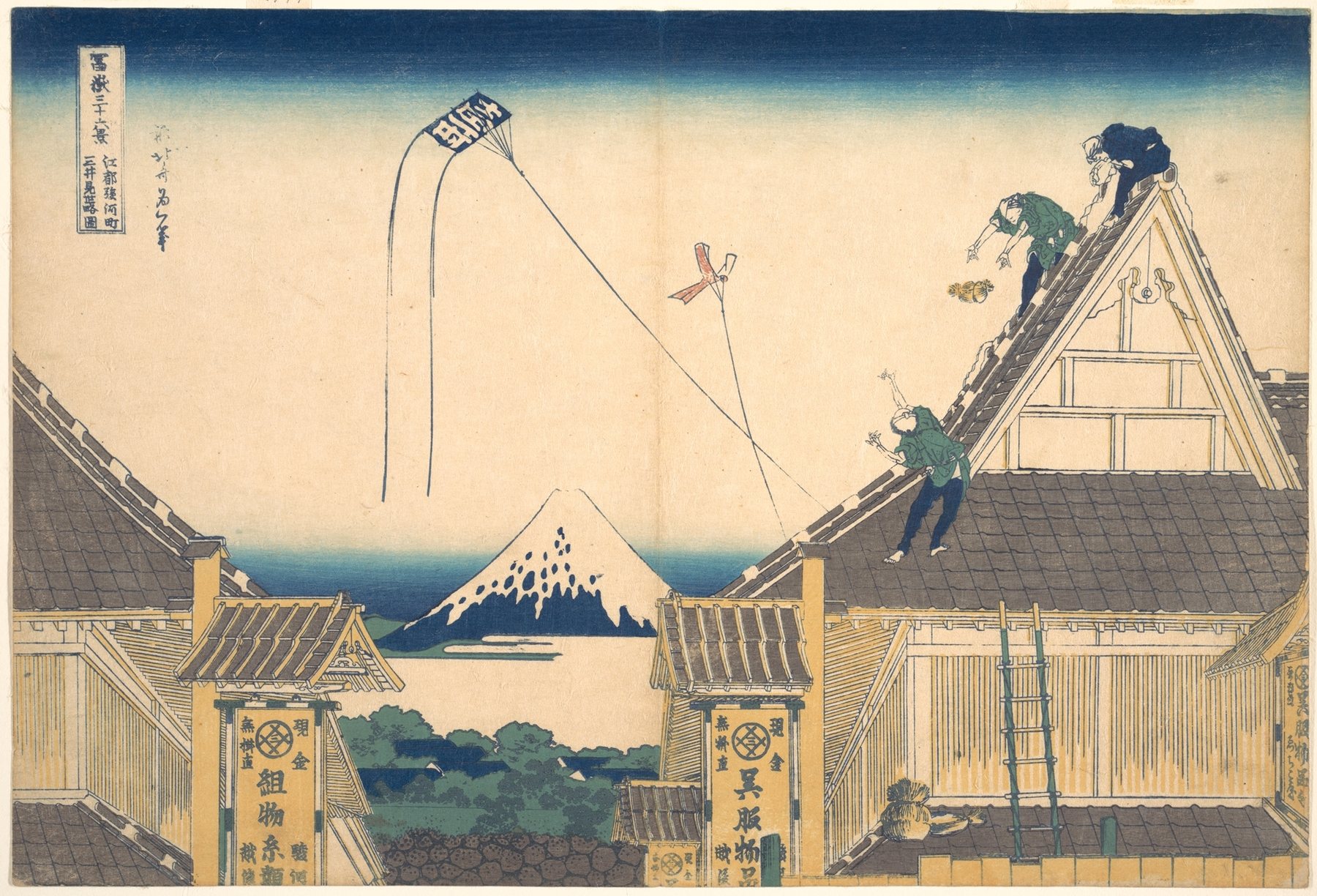
Hokusai's Met print Mitsui Shop at Surugachō in Edo, dated about 1830–32, is an urban picture, not a building commission drawing. The lively commercial fronts on either side frame a distant prospect, and their repeated directions guide the viewer through a recognisable Edo street. The museum's Japanese title, date and print medium keep its context attached. It should not be introduced as a hidden example of western architectural drafting simply because it uses a strong axis. It shows that architectural forms and routes can make a viewer's attention move in a print intended for a broader pictorial audience. [21], [22]
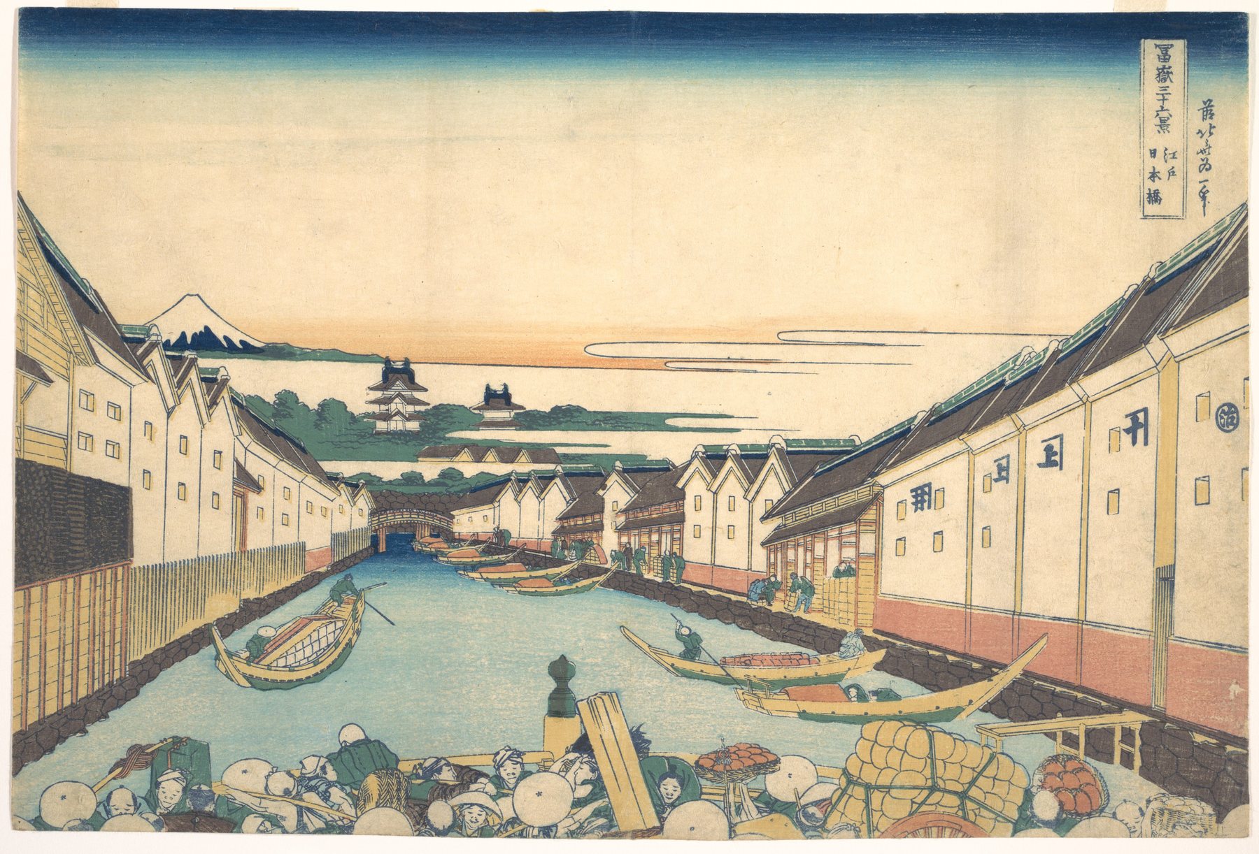
The same series' Nihonbashi in Edo uses a named bridge and urban axis to set the city against distant Fuji. Its cityscape is an argument about place, identity and visual reach as well as a depth effect. In each print, lines are selected and arranged by a maker who chooses what should draw the eye. These are not interchangeable with Tessenow's German design arguments or Boullée's French civic ambitions, but they confirm that built form can organise pictorial meaning outside a single European treatise lineage. The Met's account of an early-eighteenth-century Guler court folio offers another distinct spatial practice: a fortress in a narrative scene is made comprehensible through multiple vantage points, so complex action can coexist on one page. That is not a defect to be scored against one-point construction. [21], [22], [23], [24]
What a perspective can prove, and what it cannot
The visual evidence of a perspective begins with its paper object. Maker, date, medium, title, inscriptions, repository, publication history and relation to a project decide what the picture can testify to. A Met stage set drawing with visible leadpoint construction proves a maker worked toward an illusion, not that an audience saw it. The BnF's large Boullée drawing proves a first Cirque proposal was developed and preserved, not that its geometry was erected. A CCA preliminary Toronto sheet proves a 1938 proposal existed and, because the archive says unexecuted, actively prevents a built-building claim. Conversely, a drawing of an existing Kew building from a named lawn station can be compared with plans, photographs and surviving fabric to test what its appearance recorded or idealised. [12], [20], [28], [32]
In heritage documentation the evidential difference becomes procedural. The United States National Park Service defines a measured drawing as a depiction of existing conditions under specified survey guidelines and a large-format photograph as a different kind of record with perspective distortion corrected where appropriate. Its laser-scan guidance explains that point clouds are supplemented with traditional hand measurement and processed into two- or three-dimensional measured drawings. Even a modern photorealistic rendering cannot simply inherit the authority of these records. A model may be precise about its known inputs while silently filling missing structure with an assumption. A drawing can make that uncertainty visible by showing an inferred part distinctly; a beautiful perspective may conceal it unless the caption and companion records tell the reader what was observed. [25], [26]
Viewpoint is thus an ethical and historical matter as well as a geometric one. The architect can place the eye at a child's height, behind a public entrance, above a private garden or out in a city street. Each station brings some people and routes into sight and leaves others beyond the frame. Adding a person for scale can imply who is expected to use a building; omitting workers or service spaces can make a complex structure appear effortlessly available. Reading a perspective alongside plan, section, site record and project chronology does not destroy its poetic power. It lets the image retain its real status: a selected, often brilliant argument about how architecture might be seen, used or imagined. [1], [2], [7], [13], [17], [18], [19], [20]
Explore RELATED Artworks and Records
Four further perspective sheets separate stage, project and workshop purposes.
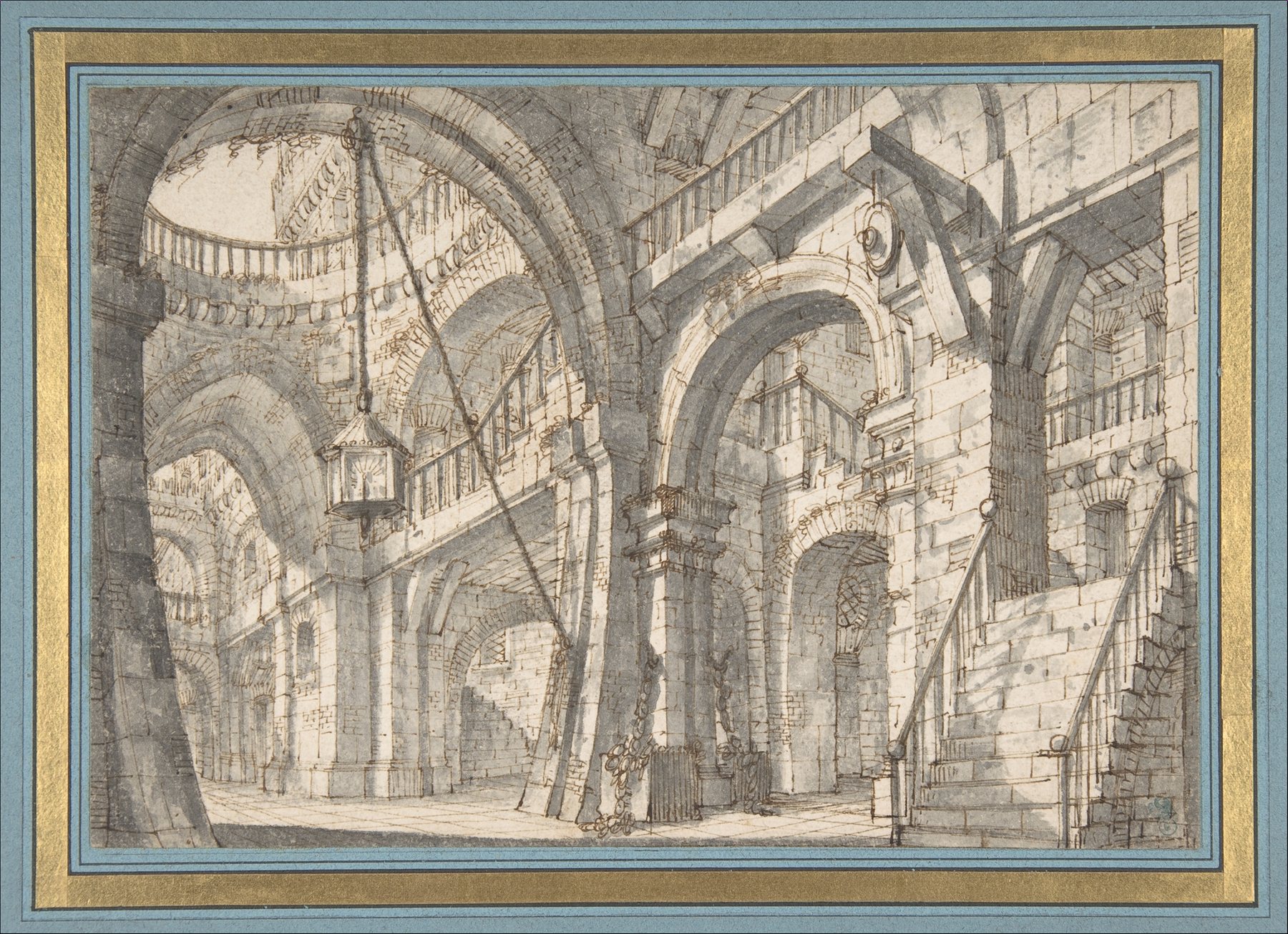
Stairs and arches
Brizzi’s scenic recession.
The Met · public-domain object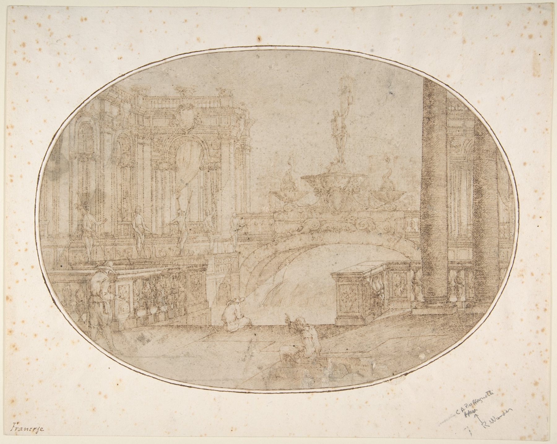
Bridge and fountain
Buffagnotti’s staged deep view.
The Met · public-domain object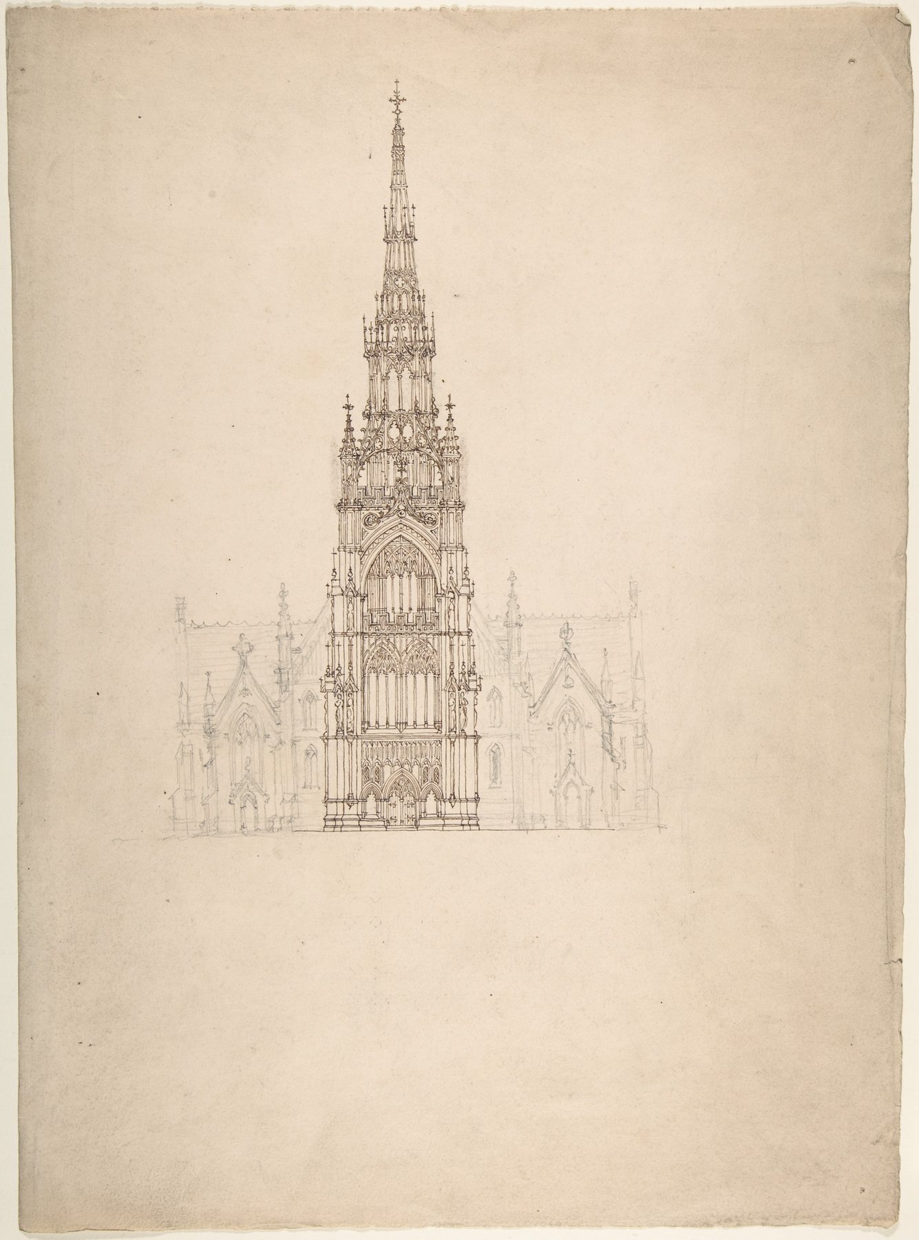
Decorated church
An anonymous nineteenth-century project.
The Met · public-domain object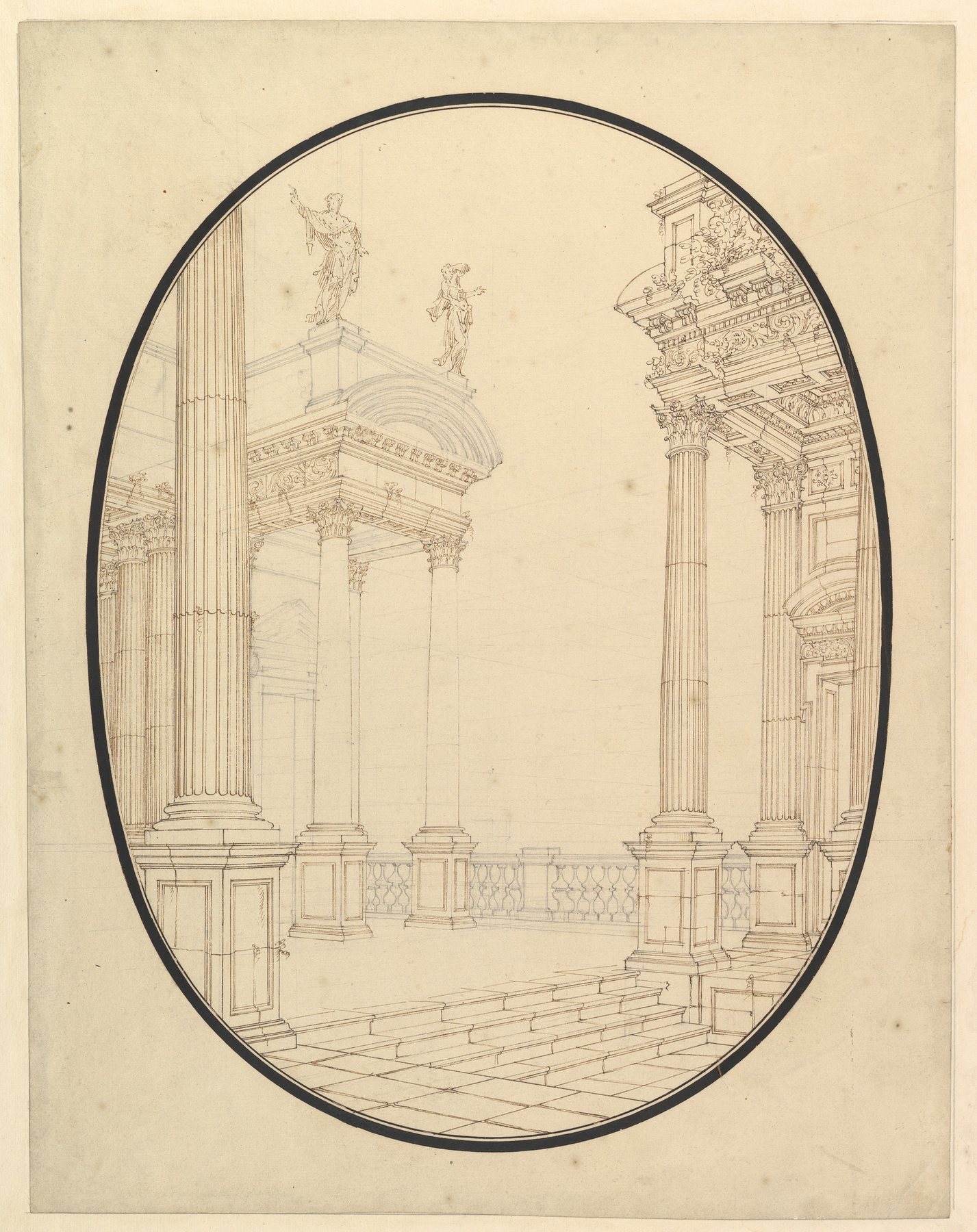
Oval palace porch
Workshop drawing, not Ferdinando’s autograph.
The Met · public-domain objectWatch: Perspective and Viewing Space
Three distinct institutional films on angle-dependent illusion, drawn geometry and moving viewpoint.
De Artificiali Perspectiva
Anamorphosis makes the dependence on viewing angle vivid.
Original illustrated preview, not a film still.
Reconstructing a Gothic Vault Design
Historic architectural drawing geometry; not a Renaissance perspective lesson.
Original illustrated preview, not a film still.
The Met 360° Project
Moving viewpoint through museum architecture, distinct from a fixed drawing.
Original illustrated preview, not a film still.Frequently Asked Questions
Each family of parallel spatial directions has its own point; level ground-plane directions lie on the appropriate horizon line. [1] [2] [3]
No. The labels describe how a rectilinear subject is oriented relative to a selected station. [1]
Not directly. Central projection generally loses true lengths, angles and depth unless calibrated by other information. [2] [25]
No. His reported demonstration is historically important, but original panels are lost and other spatial conventions existed. [4] [7] [21] [24]
BnF and Met records date the bilingual Paris Books I–II edition, with Jean Martin translation, to 1545. [5] [6]
No. A drawing may be a stage set, capriccio, preliminary project or explicitly unexecuted scheme. [12] [20] [27] [28]
References
- Columbia GSAPP, Projection.
- MIT Computational Photography, Pinhole Image Formation and Linear Perspective.
- Art Institute of Chicago, What Is Perspective?.
- The Metropolitan Museum of Art, Architecture in Renaissance Italy.
- Bibliothèque nationale de France, Serlio Books I–II early-print record.
- The Met, Serlio's printed Books I–II, object 380554.
- RIBA, The Power of Perspective collection story.
- RIBA, Antonio Visentini drawings catalogue.
- CCA, Du Pérac's Campidoglio perspective.
- The Met, Andrea Pozzo's perspective treatise.
- Uffizi, Sala dell'Udienza pubblica.
- BnF, Boullée's Cirque perspective elevation.
- TU Delft, Zeinstra, Thinking Perspectives.
- CCA, Cedric Price student drawings.
- RIBA, Anthony Cox student drawings.
- The Met, Laying New Foundations: Paul Rudolph.
- CCA, Potteries Thinkbelt archive.
- CCA, PREVI Lima archive.
- CCA, Isozaki Marunouchi aerial view.
- CCA, proposed CBC Studios preliminary perspective.
- Kyoto University repository, Takashina's Edo urban-image article.
- The Met, Hokusai Mitsui Shop.
- The Met, Hokusai Nihonbashi.
- The Met, Indian Skies: Hodgkin Collection.
- National Park Service, Secretary's documentation standards.
- National Park Service, Laser Scan Guidance.
- The Met, Piranesi's staircase perspective etching.
- The Met, Antonio Mauro's scenic cityscape.
- The Met, circle of Ferdinando Galli Bibiena scenic courtyard.
- The Met, anonymous architectural ceiling perspective.
- The Met, anonymous column-base perspective exercise.
- The Met, Joshua Kirby at Kew.
- The Met, Rochead Glasgow church perspective elevation.
- The Met, Open Access policy.
- The Met, De Artificiali Perspectiva film.
- The Met, Reconstructing a Gothic Vault Design film.
- The Met, 360° Project films.
Explore RELATED Architecture
These built-place pages show why plans, perspective, photographs and later records must be read together.
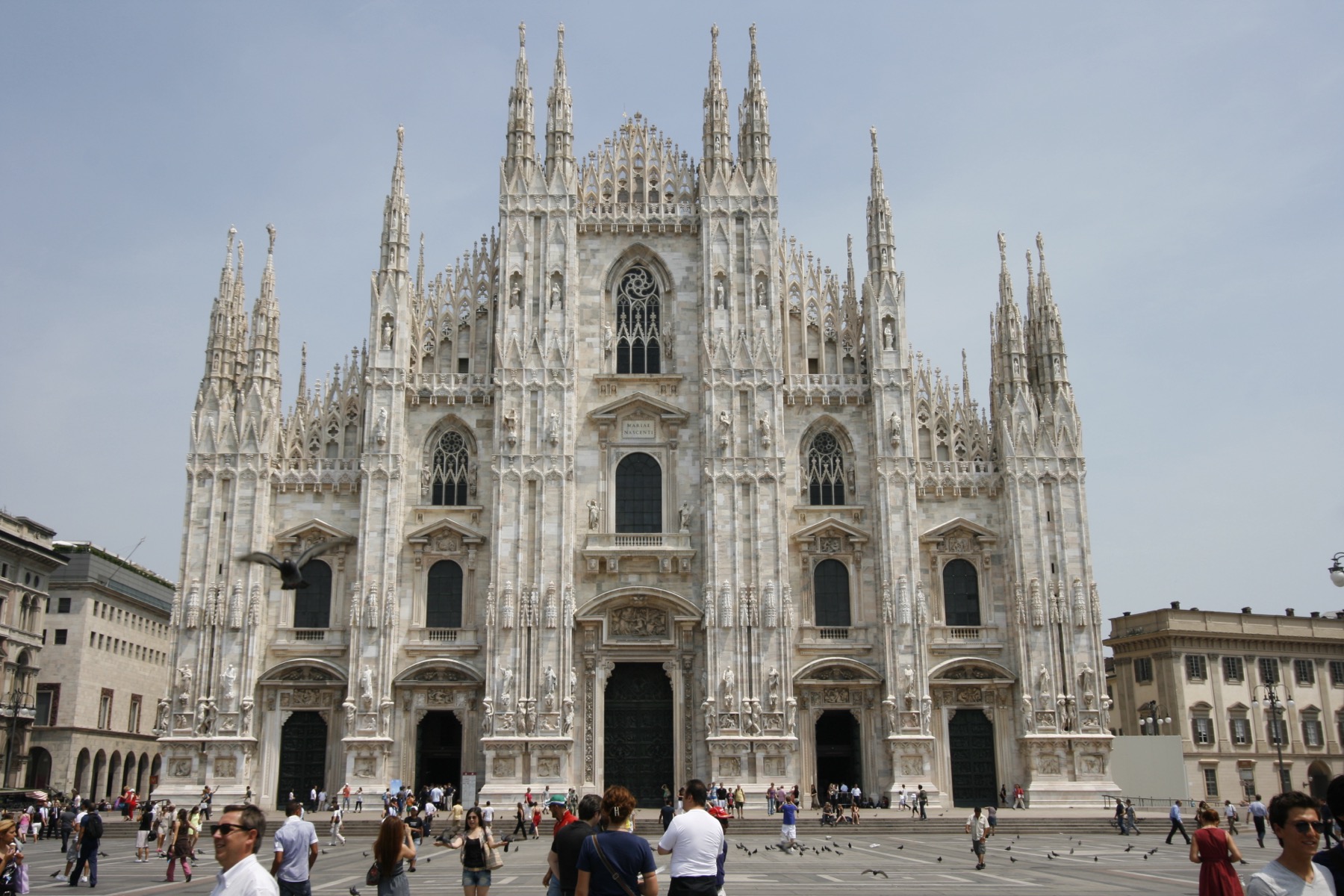
Milan Cathedral
Front, tower and long construction history differ from one selected vista.
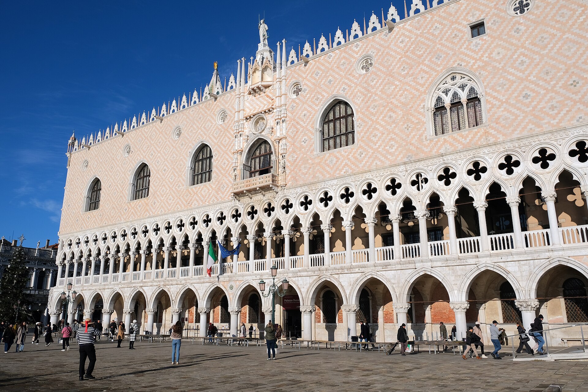
Doge’s Palace
Venetian vedute and its altered fabric require separate evidence.
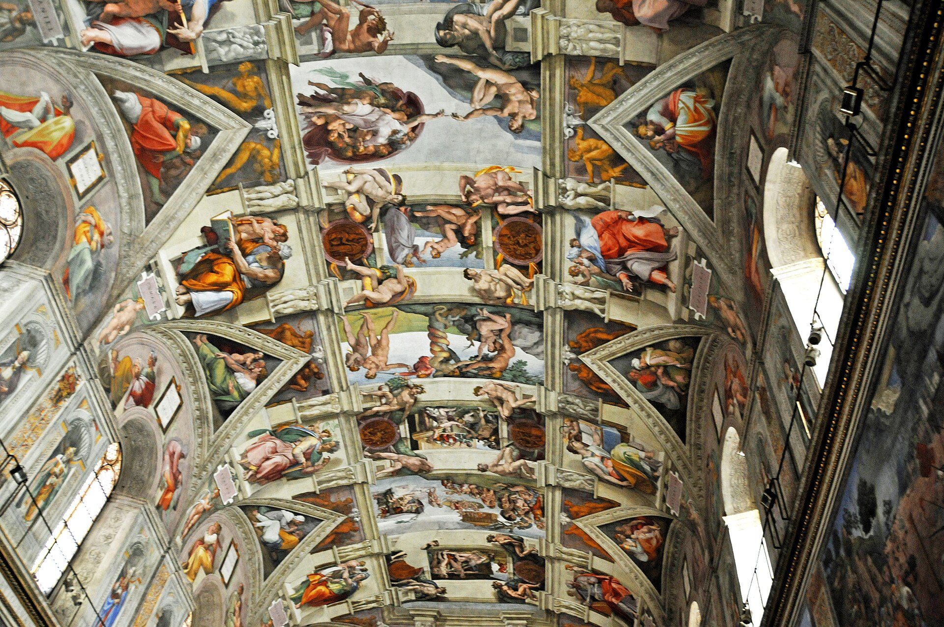
Sistine Chapel
Painted space and building shell can be read in different ways.
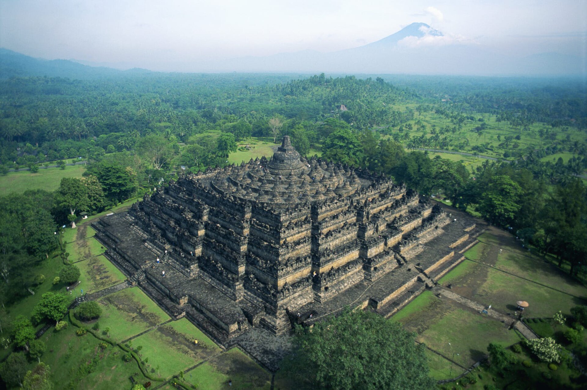
Borobudur
Aerial and visitor-level views disclose different spatial relations.
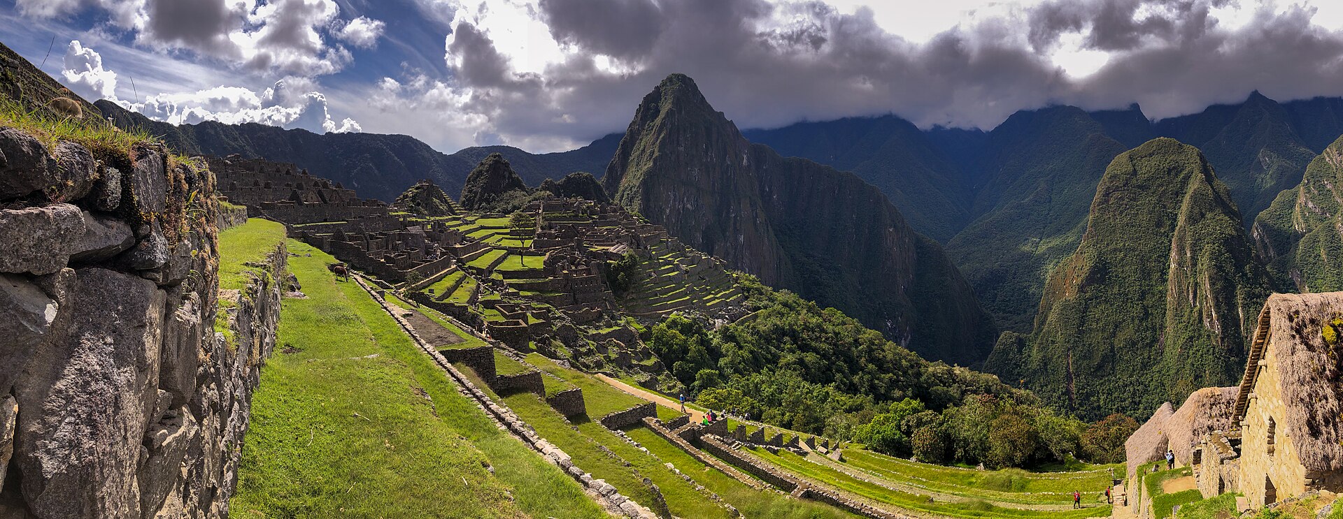
Machu Picchu
An elevated view organises ruins but cannot replace measured records.
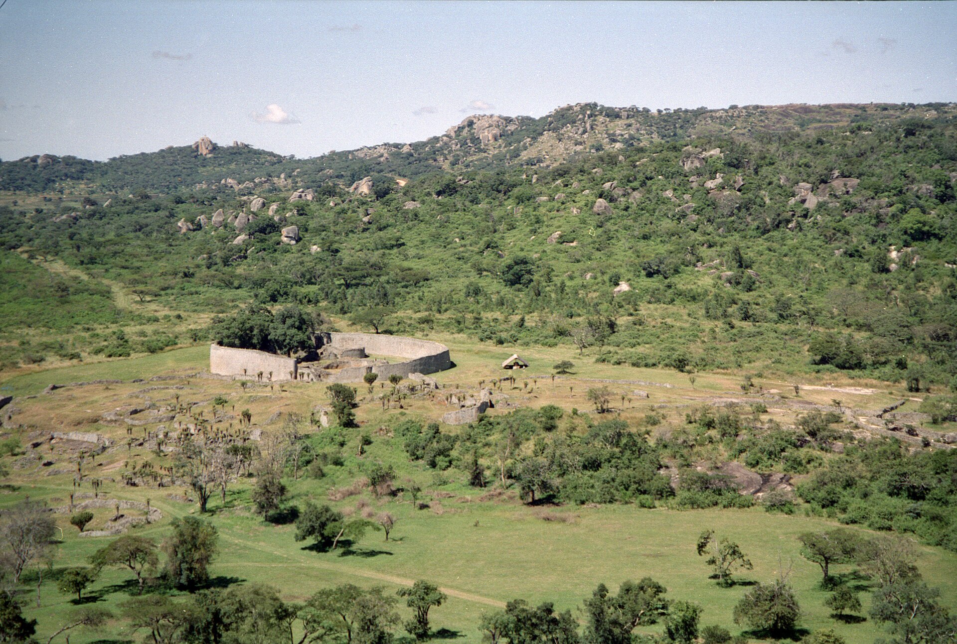
Great Zimbabwe
A single view cannot settle a complex site’s full sequence.
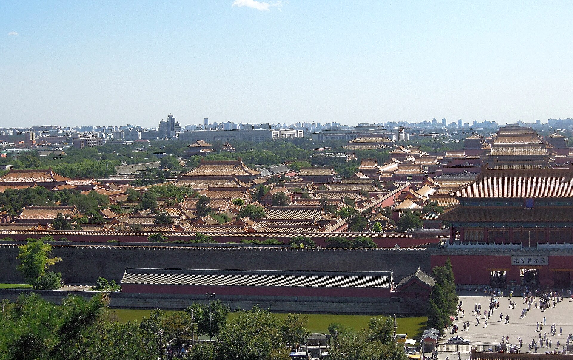
Forbidden City
Court axes and roof views frame different palace readings.
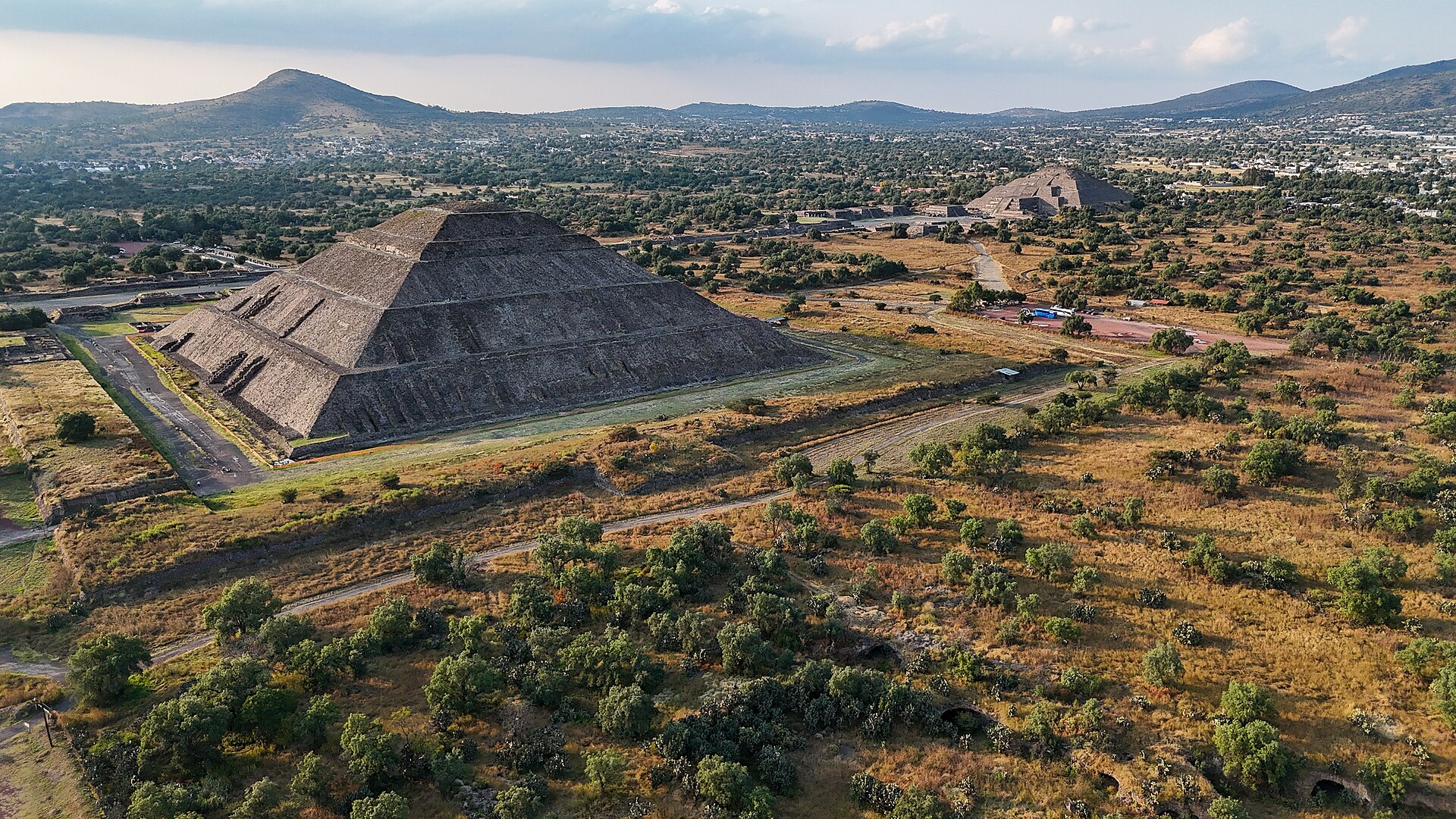
Teotihuacan
An urban axis may organise attention without documenting every structure.