


 by Tom Gurney
Tom Gurney BSc (Hons) is an art history expert with over 20 years experience
Email: tomgurney1@gmail.com / Phone: +44 7429 011000
Cut, Proposal, Record and Reader
A plan lets us think about a building that cannot be seen all at once. It can arrange rooms on paper before they exist, guide work at a particular floor, record walls encountered in a later survey, or persuade readers of a printed book that a design is coherent. Its apparent simplicity is deceptive. What looks like a view from above is usually a selective horizontal cut through a building, made at a chosen level and according to conventions that have changed with audience, period and purpose. A staircase may appear differently on two floors; a roof might need another drawing; a dashed line can represent something overhead, demolished, proposed or merely inferred. None of these marks makes sense without the particular sheet. [1], [17], [18], [21]
The histories of plans are consequently histories of decisions and documents, not just geometries. An annotated Carolingian monastery diagram was an ideal arrangement, not a measured record of the present St Gallen abbey. A Renaissance print could shorten a garden to fit a book page. A coloured nineteenth-century Paris plan could propose changes to a house already standing. In Japan, a joined-sheet palace copy made in 1843 records a later inspection, not the building’s first design. And an American measured plan drawn in 2009 cannot be assigned to the architect who designed the older house it depicts. These are different uses of the same broad visual family. To read one responsibly, we must ask when, by whom, from what evidence, for what audience and with what relation to construction it was made. [4], [5], [8], [9], [10], [11], [19], [22]
At a Glance
- What it showsA chosen horizontal section through space, rather than a simple overhead photograph. [18]
- First questionProposal, working instruction, publication, later survey, copy or reconstruction? [1], [4], [5]
- LevelsGround, upper, basement, roof and site plans answer different questions. [15], [18]
- Reading keysLook for cut height, scale, orientation, symbols, dimensions and revision or source notes. [2], [18], [21]
- HistoryA surviving plan need not represent what was actually built. [8], [9]
- AudienceSymbol, pictogram, colour and three-dimensional cues may help different tasks differently. [17]
- Other viewsSection and elevation may clarify heights or faces hidden from the plan. [5], [18]
- Record statusCopy, print and measured survey each have dates distinct from the original project. [4], [5], [11], [19]
Contents
- A cut through a place, not a bird’s-eye view
- Scale, orientation and the plan’s graphic grammar
- The St Gallen monastery plan and an imagined community
- Renaissance plans: observation, proposal and printed persuasion
- Negotiating the plans of San Firenze
- Houses, patrons, gardens and alternatives
- Japanese plans, copies and joined sheets
- Plans drawn after buildings were changed
- What a plan reader can actually learn
- The plan as an architectural witness
A cut through a place, not a bird’s-eye view
The conventional building plan is often explained as a horizontal slice seen from above. That description is useful, but it should immediately raise a second question: at what height was the slice taken? Walls, doors and windows do not occupy the same shape at every level. A high cut can encounter a window where a lower cut would show solid wall; a floor above can change which stair treads and landing are relevant; an arch may sit above the chosen line but matter spatially. Many drawings combine the heavy lines of cut material with lighter information projected from above or below. The mixture makes a plan legible, not optically literal. [18], [21]
The US National Park Service’s Historic American Buildings Survey provides a deliberately specific example. Its measured-drawing guidance normally locates survey-plan measurements about four feet above the floor, but allows the measurement string to jog to catch a window’s lower sash or a fireplace’s maximum opening. It instructs surveyors to measure room walls continuously from corner to corner, collecting door, window and fireplace positions; diagonals help fix irregular rooms; long strings through doorways help establish wall thickness. This is a precise heritage-documentation practice for observed American buildings. It is not a proof that every architect in every culture cut every plan at four feet, or that every graphic line on a historical plan refers to an identical cut height. [18]

Text alternative for the diagram
An invented side wall and invented room plan illustrate cut-level selection. The four-foot HABS survey convention is specific to its US guidance.
The act of selection can be informative or dangerous. An attic may be omitted because the commission concerns the ground floor, or because a printer has room for one plate, or because the archive preserved only one sheet of a larger set. The resulting plan might look whole when it is not. Reading labels such as “first floor”, “ground plan” or a stated level matters more than assuming a drawing represents every storey. A plan can also isolate a column base, a portico or a funerary structure rather than a house: architectural plan-making occurs at multiple scales, each with a different object. [1], [15], [24], [26], [27], [28], [29], [30], [31], [32], [33], [34], [35]
Scale, orientation and the plan’s graphic grammar
The plan’s claim to precision depends on evidence that is easy to overlook in a small reproduction. A scale may be a ratio, a bar, a quoted dimension or no scale at all. A north arrow can orient a site drawing, but not every plan carries one. A thickened line may signify material cut by the section; a thinner line might indicate what lies beyond. A stair arrow could denote direction of ascent in a particular office convention, but it is unsafe to supply a key from habit where the sheet gives none. Graphite construction beneath ink, washes and later annotations can represent different moments of making. The legends, notes, sheet title and edition history belong to the visual argument. [1], [2], [18], [21]
Politecnico di Milano’s Italian Piero Bottoni archive demonstrates why cataloguing must be checked rather than repeated uncritically. A 1924–25 academic residence exercise has a basement-and-sewer plan, ground and upper plans, sections and details at different sizes. The archivist notes that one basement drawing listed as 1:100 is actually 1:50. The correction changes how one would compare it with other sheets. Just as important, the sheets were educational work, not documentation of an executed domestic commission. An exact-looking scale on a project file does not turn a teaching exercise into a built house. [15]
The archive also preserves Bottoni’s approximately 1928 Viale Argonne neighbourhood study. Its plotted housing arrangement belongs to preparatory urban thought before a competition he did not enter. The plan can speak to the architect’s interest in block and street form without becoming evidence of a commission, a submitted entry or realised housing. A site plan occupies a different scale from a room plan, but its documentary status still needs the same care. [16]

Text alternative for the diagram
Two schematic levels show a stair position and upper landing. They do not redraw Degana’s sheets.
Contemporary working-drawing guidance makes a related, but differently situated, point. The American Institute of Architects asks for dimension and symbol legibility, consistent references from plans to details, coordination among disciplines and clear revision information. Its published checklist is explicitly a member-contributed, non-exhaustive guide. A plan’s door location must agree with a wall detail, a services or structure sheet and written specifications for construction information to be reliable; the plan alone cannot carry every performance requirement. These conventions describe a professional working set, not a rule that can be retroactively imposed on a Carolingian manuscript or an eighteenth-century book illustration. [21]
The St Gallen monastery plan and an imagined community
The famous St Gallen parchment is a strong antidote to the idea that a plan is always a survey. The Stiftsbibliothek catalogue dates the Carolingian document approximately to either 819 or the later 820s, associates it with Reichenau, and describes five sewn pieces of sheep parchment carrying an annotated arrangement of 52 buildings. The abbey compound imagines church, housing and work within an organised monastic life. The document was reused: later writing occupies its reverse, and its folding and binding are part of the history by which it survived. It has an original graphic purpose and an afterlife as an object. [8]
The plan is an ideal arrangement, not an accurate floor-by-floor drawing of the abbey now visible at St Gallen. UNESCO’s account likewise treats it as an ideal Benedictine complex; the present monument has many much later phases. Dating the parchment precisely remains a scholarly matter, and even inscription totals differ between institutional descriptions because they count different categories of writing. The point for an architectural history is not to settle the count by fiat or call this the “first plan in the world”. It is to see how annotations, building relations and later material reuse make the sheet a witness to a particular vision of monastic order rather than a photograph of construction. [8], [9]

Text alternative for the diagram
Invented blocks contrast programme and later fabric; this is not a transcription of Cod Sang 1092 or the present abbey.
Written labels matter to that vision. A building form is not necessarily self-explanatory; its intended function or adjacency can be stated alongside the lines. The plan can therefore carry a programme for daily life—work, prayer, accommodation, circulation—as well as an arrangement of walls. That relationship between graphic division and social use recurs in later palaces, houses, mosques, hospitals and schools, although the conventions and purposes of their plans are not identical. We should not treat an early European survival as a standard against which other architectural cultures must be measured. [8], [10], [12], [13], [14]
Renaissance plans: observation, proposal and printed persuasion
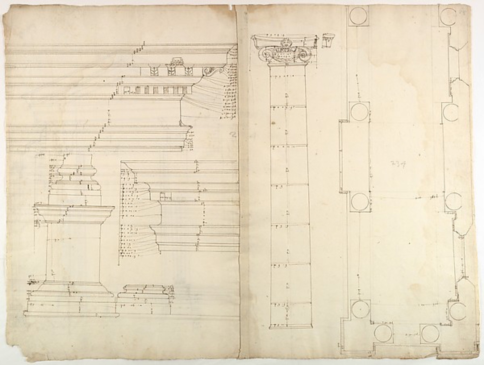
Renaissance architects did not only draw new buildings. At the Uffizi, Giovanni Antonio Dosio’s study sheet of the Temple of Antoninus and Faustina records a plan and measurements of ancient fabric on one side, with an elevation and capital on the other. It uses drawing to examine a monument already standing in fragmentary form. The inscription is part of the evidence. Nothing about its Renaissance date makes it the original plan from the Roman builders; nothing about an intended treatise proves that the book was completed. [6]
The relationship between a plan, another view and a later printed page is even more intricate in Andrea Palladio’s Quattro Libri of 1570. In a full TU Berlin dissertation, Lorena Cristina Valdivia Steel reads the woodcuts as crafted book objects. Of the volume’s 216 woodcuts, only six are simple perspectives; plan, elevation and section are often chosen, but their arrangement is not a frozen universal template. In one case the Palazzo Valmarana garden is shortened in the published representation to fit plan and elevation on the page. For a Battistero di Costantino plate, the printed relationship of plan and elevation differs from a preparatory sheet held by RIBA. Other plates overlay or reposition views. These are particular cases studied from surviving sheets and publication, not permission to assume every Palladian drawing falsifies a building. They demonstrate that a book can make an argument through page fit and visual comparison. [3], [4]

Text alternative for the diagram
Invented source sheet and print-page boxes represent a possible layout decision, not a facsimile of Palladio’s Palazzo Valmarana plate.
The publication’s audience is not the same as a carpenter on a site or a patron choosing between alternatives. A printed plan can travel widely and be reread as exemplary architecture; its original setting-out or revision marks may be omitted. It can shape how a project enters history even when the walls, costs and phases took another path. To reconstruct a building decision, a historian should compare the plate with preparatory sheets, archival descriptions and the fabric rather than promote an attractive woodcut to a definitive as-built document. This is an inference from the specific dissertation cases and the museum’s broader account of drawings’ multiple audiences. [3], [4]
Negotiating the plans of San Firenze
The Uffizi’s Italian study of San Firenze in Florence shows more directly that a plan is a proposal made amid institutional and financial pressure. Pietro da Cortona’s relatively small 1644 plan, GDSU 2252A, is a documented starting point. An intermediate 1645 plan is lost: the stage is known from documents and related evidence, not from a sheet we can inspect. A more ambitious arrangement surviving as GDSU 2251A is a 1658 copy by Carlo Morosi after Cortona’s project. It should not be captioned as Cortona’s autograph merely because the design history points back to him. [5]
Pier Francesco Silvani subsequently worked to reduce or “moderate” the scheme as funds and requirements changed. Doors, columns, side arrangements and the relation between patrons and Oratorians became questions of space and expense, not just stylistic taste. The Uffizi article inventories 41 surviving project drawings—11 plans, 20 longitudinal sections, three transverse, six detail sections and one facade—beside a wooden model. Some plans and sections lack a firm date or scale; some intermediate schemes are missing altogether. Matching the nearest-looking views as one flawless “final design” would manufacture certainty the archive does not have. [5]

Text alternative for the diagram
The timeline gives documentary status, not a compulsory design sequence. The surviving 1658 plan is a Morosi copy after Cortona.
Around 1668–70, a plan and section closely approach a model for a revised scheme, but that scheme was only partly executed and later changed. Looking at several plans in sequence reveals negotiations over the same place; looking at fabric and documents tests which line became masonry. This is not a general claim that architecture always proceeds from small plan to grand plan and then economical reduction. San Firenze is a specific case in which the institution’s article can identify dates, copies, patrons and missing steps. Its complexity is precisely why a single reproduced floor plan cannot stand for “the church as built”. [5]
Houses, patrons, gardens and alternatives
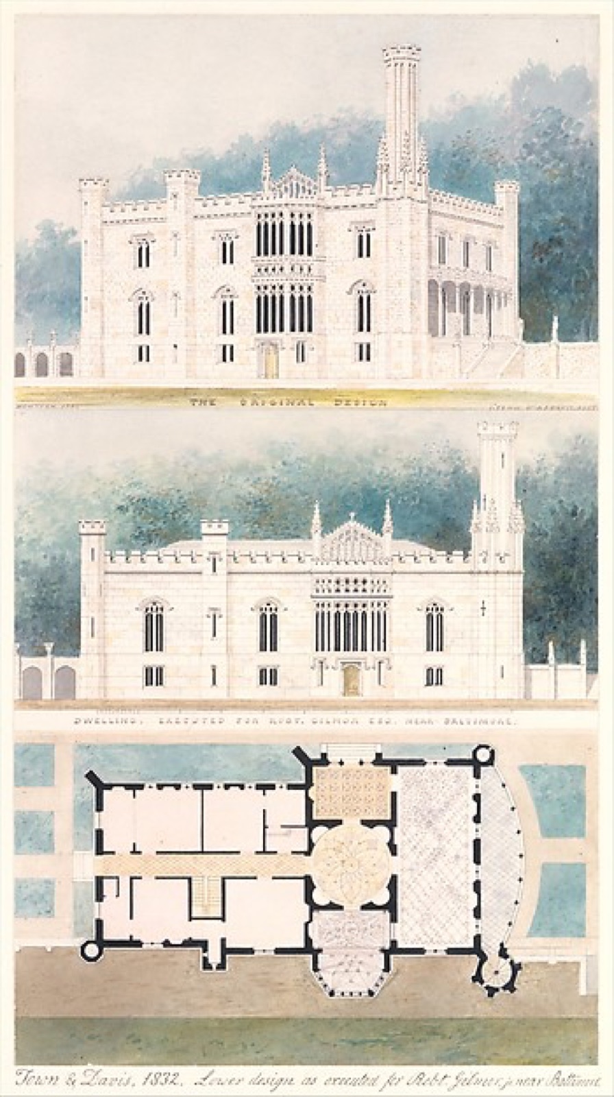
Plans are also a way of negotiating an individual household. The Met’s drawing for Glen Ellen, Maryland, joins perspective, elevation and plan in a picturesque house proposal of 1832. Its record attributes the cruciform floor-plan conception to Ithiel Town and the patron Robert Gilmor, while Alexander Jackson Davis shaped the Gothic ornament. A prominent draughtsman’s signature and style therefore do not exhaust the authorship of spatial decisions. The house was built and later demolished; a surviving proposal can help explain it, but ought to be compared with other records before being treated as a measured account of the final fabric. [23]
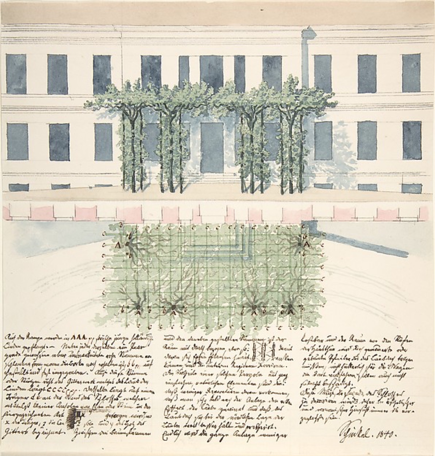
Another Met sheet, an undated plan by Jean Jacques Huvé for the Hôtel de la Rochefoucauld Doudeauville in Paris, concerns adjustment to a residence erected in 1732 by Jean-Sylvain Cartaud. The unusually long paper extends the room arrangement into the garden. The museum describes Huvé’s commission for the comtesse de la Suze and regards a garden belvedere as probably his responsibility. That probability should remain a probability in the caption. This is an alteration proposal to an existing house, not evidence that Huvé designed the 1732 original or that every coloured zone denotes a fixed construction stage. [22]
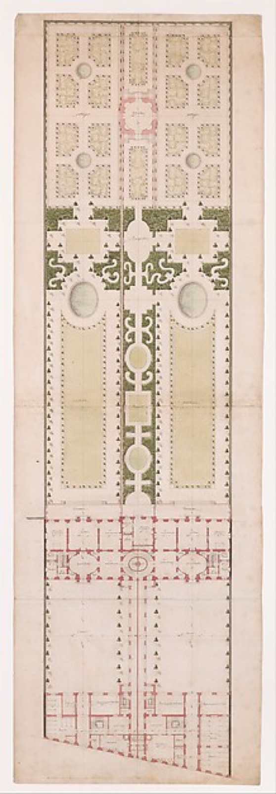

Text alternative for the diagram
Invented house and garden rectangles only explain the relationship; they are not Huvé’s measured geometry.
The BnF’s item record for Henri Labrouste’s proposed great stair of the Bibliothèque impériale makes alternatives visible even in a sheet containing plans and sections. It also includes perspectives and croquis showing different possible stair routes. The catalogue dates it around 1869, but the sheet is unsigned and undated; its exact authorship/date cannot be read off an elegant wash. Several views on one piece of paper may be a discussion among options, not a uniquely settled instruction. This lesson complements Glen Ellen’s shared design work: a plan often has a social and tentative status, even when its lines appear meticulous. [7]
Japanese plans, copies and joined sheets
The Nakai carpenters’ archive at Kyoto University reminds us that architectural plans traveled through other material and administrative traditions. Its palace subset includes plans, sections, elevations, repairs and okoshi-ezu sheets that can be lifted into spatial form. A flat Western “floor-plan” definition is a useful point of comparison, but it should not erase the way these documents were folded, joined, annotated, copied and consulted. Nor can one fold-up item establish that every Japanese palace project used the same technique. The repository’s own Japanese record supplies the item terms and documentary context. [10]
A Ninomaru palace drawing for Nijō Castle, Kyoto University RB00021808, is especially clear about status. The catalogue dates this coloured, nine-joined-sheet kōzo-paper copy to Tenpō 14, or 1843, and describes it as copied for investigation. Its roughly 69 by 77 centimetre sheet has a date in the Nakai family record, not a certificate of the palace’s original construction. Its plan can carry knowledge of rooms and later survey purposes, while its copy status requires attention to the source from which it was transcribed and the condition being examined. [11]

Text alternative for the diagram
Three document/date statuses are distinct; the 1843 Kyoto copy dates its investigation, not initial Nijō construction.
The Japanese case sharpens a broadly useful question: which date belongs to which thing? An earlier building, an altered state, a first drawing, a copy, a repair file and a digitised surrogate need not coincide. Exact-looking ground lines do not tell us whether a maker projected a future room, observed a present one or transferred an earlier sheet. The answer comes from catalogue description, inscriptions, related evidence and the physical or digital object, not by applying another archive’s conventions across cultures. [1], [2], [10], [11]
Plans drawn after buildings were changed
The modern heritage plan can be a close observation of walls that no architect at the initial design stage could have known. Historic American Buildings Survey and related Library of Congress programmes publish measured drawings with photographs and written histories. In the Library’s discussion of Louis Kahn, a 2009 measured plan of the Margaret Esherick House is explicitly not Kahn’s original or automatically its initial as-built plan. Later interventions may separate the surveyed condition from the designed one. An as-found plan can still recover a powerful spatial account, particularly when a building has vanished, but its evidentiary date is the survey date. [18], [19], [20]

Text alternative for the diagram
An invented solid observed wall and dashed inferred earlier line illustrate source status; not a HABS sheet facsimile.
Measurements are not the entire story. The NPS guidance calls for careful corner-to-corner strings and diagonals where necessary, while heritage interpretation may also need field notes, photographs, documentary history and distinct marks for inferred earlier phases. A convincing historical reconstruction is not an observed wall. Likewise, Archnet’s catalogued CAD floor plan of Aleppo’s Kamiliyya Madrasa is a modern scholarly drawing of a historic Islamic building, not a medieval original sheet; Afghanistan house records made by Aga Khan Cultural Services have another conservation/documentation status; and Al-Aqsa restoration drawings preserved in an award file document a later intervention. The building’s date, survey or restoration date, and archive date must be allowed to differ. [12], [13], [14], [18], [19], [20]
What a plan reader can actually learn
The well-known claim that plans are “hard for nonarchitects” needs more precision. Soranart Sinuraibhan’s University of Sheffield doctoral study tested responses to different drawings of one first-floor domestic flat. Participants were self-selected Sheffield staff and students, alongside first-year and diploma architecture students; plans were at the same scale and orientation. In one set of valid lay responses, a pictorial version was most often judged easiest at first glance (43.32 percent), while a three-dimensional version scored best for a room-relationship question (44.28 percent). For a circulation question, the more conventionally coded Plan A was most frequently successful (44.77 percent). A pictorial plan was strongest for identifying building use (78.81 percent). Different questions had different winning representations. [17]
The study’s later semi-diagrammatic colour-and-circulation version often helped respondents, but some visual additions could clutter rather than clarify. One comparison even favoured the conventional plan for circulation over the coloured variant; it compared questions from different tests, not two perfectly isolated versions of the same question, so it cannot establish a clean universal causal effect of colour. These results belong to one flat, one university recruitment pool and specific questions. They do not tell us the preferences of every public visitor, historic patron, contractor or preservationist. Their broader, defensible lesson is task sensitivity: to locate a path, understand room relations or recognise use may call for different levels of code, pictogram and spatial cue. [17]

Text alternative for the diagram
The graphic maps specific first-test tasks to A coded, C three-dimensional and B pictorial; it is not a universal reader ranking.
A viewer of a historical plan may need more than its linework to understand what is shown. The stated cut level, whether the sheet is design or survey, and how colour is used on that particular object can change an interpretation. A second view may clarify a stair or a wall thickness. A simple geometric explanation can isolate one relationship, but cannot stand in for the dimensions, sources and marks of the actual historical sheet. [17], [18], [21]
The plan as an architectural witness
An architectural plan is most powerful when it is read with the documents and places that give it status. The RIBA catalogue’s inscriptions and provenance can distinguish a preparatory sheet from a later copy. Bottoni’s Italian archive can correct an apparent scale. The Uffizi’s San Firenze series can place a lost step between surviving plans. Kyoto University’s Japanese record can identify a joined-paper 1843 investigation copy. A BnF item can mark a sheet unsigned and undated. Each qualifies the confidence with which a line may be called original, measured, proposed or built. [1], [2], [5], [7], [11], [15]
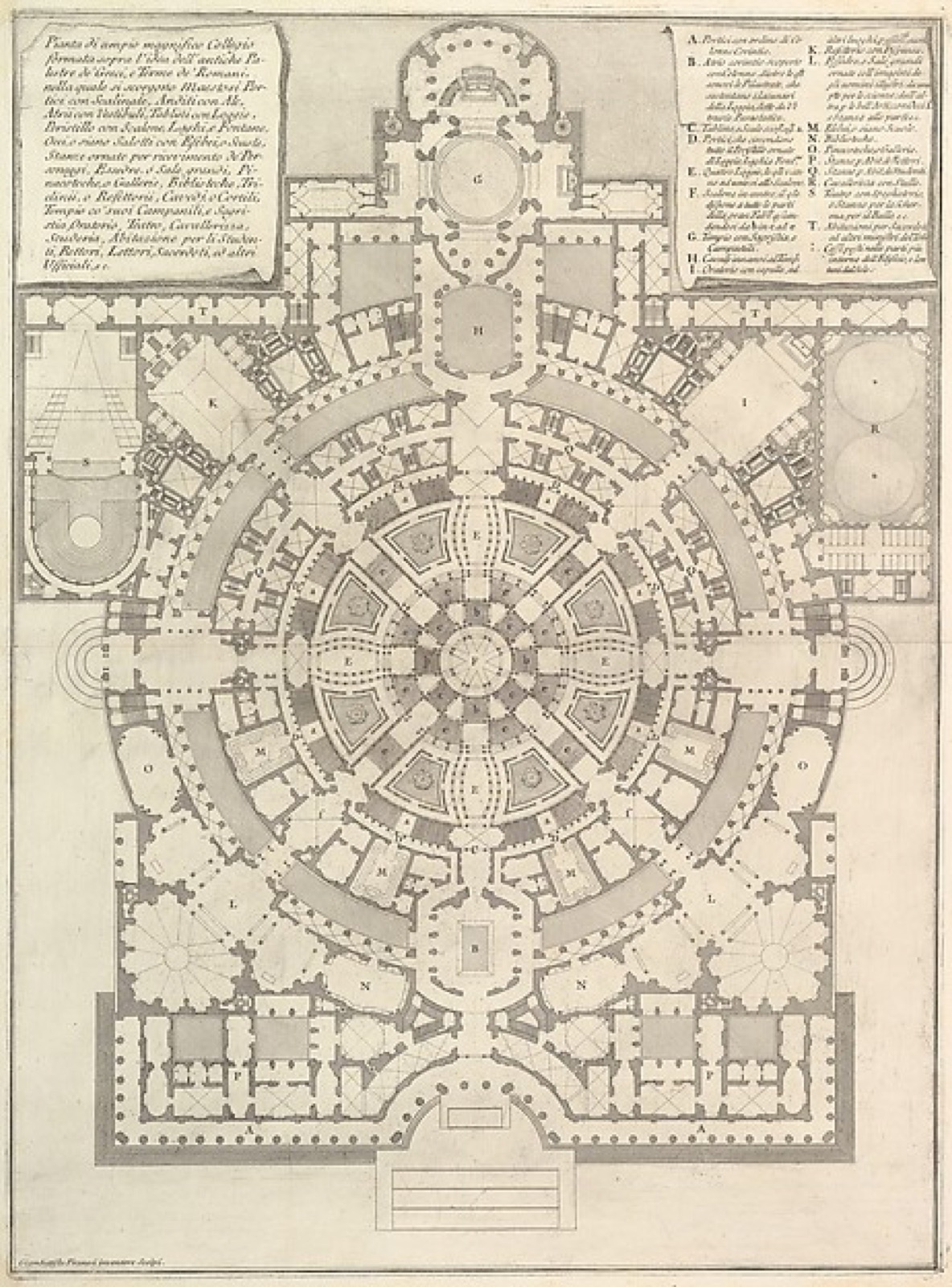
One further complication is the plan as an artwork or printed invention. Piranesi’s 1750 etched “spacious and magnificent College”, held by the Met, is a second state of a seven-state print in a visionary architectural series. It proposes and persuades through an imagined layout; it is neither an ancient survey nor a working site sheet merely because rooms and geometry are drawn carefully. Printed states themselves can change. The variety of plans on this page—proposals, studies, coloured garden arrangements, floor-specific drawings and invented print—makes no single image a neutral icon for all building practice. [24]
To test a consequential claim, begin with the plan’s maker, date, medium, repository, scale, title, status and revision or copy statement. Identify what is cut, what is projected, and whether a drawn wall was intended, observed or reconstructed. Compare the plan with a section, an elevation, another phase, specification, site photograph, field notes or surviving fabric as needed. A mismatch can be a record of changed intentions rather than a drafting error. The plan does not lose its fascination when we refuse to mistake it for the building; it becomes a richer history of people deciding what could fit, what would be built and what later generations were able to record. [1], [2], [4], [5], [7], [10], [11], [17], [18], [19], [20], [21]
Explore RELATED Artworks and Records
Four plan records with distinct dates, audiences and project status.
Piranesi’s printed college
An invented plan with changing print states.
Met Open Access object imageHuvé’s Paris house and garden
A plan for change to an older residence.
Met Open Access object imageGlen Ellen, several design hands
Plan and elevations in a shared house scheme.
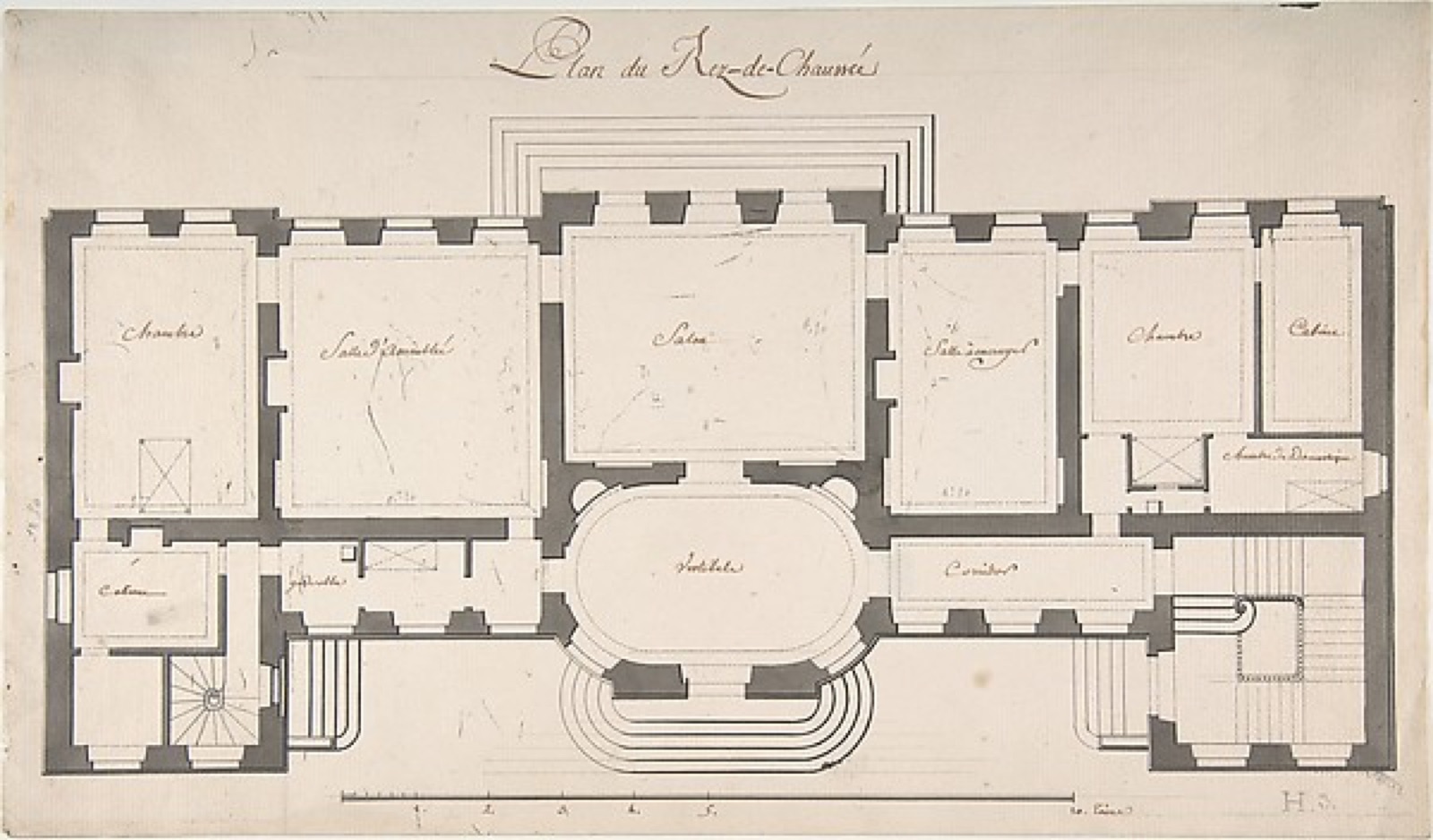
Met Open Access object imagePalace ground-floor plan
One explicitly labelled level in a plan pair.
Met Open Access object imageWatch: Architectural Plans
Institutional films and talks for geometric and spatial comparison.
Learning from Roriczer’s Pinnacle
Modern animation of a historic plan-to-elevation geometric method. [36]
Original illustrated preview; not a film still.
Reconstructing a Gothic Vault Design
Current demonstration based on a surviving Gothic design drawing. [37]
Original illustrated preview; not a film still.
Plan as Perimeter
Recorded conversation on plans and references; English with French subtitles. [38]
Original illustrated preview; not a film still.Frequently Asked Questions
No. It selects a horizontal cut and may project other features beyond that plane. [18]
It normally dates a particular document; the building, copy, revision, survey and scan may have other dates. [1] [5] [11]
Not alone. In a studied case the printed garden is shortened for page layout. [4]
No. The plan locates space horizontally; a section reveals heights and fabric along a vertical cut. [18]
No. Sheffield’s single-flat study found different formats more useful for different tasks, with limited sampling. [17]
References
- Royal Institute of British Architects, Collections Development Policy (2024).
- Royal Institute of British Architects, catalogues to the RIBA drawings collection.
- Metropolitan Museum of Art, Italian Renaissance architectural drawings curatorial essay.
- Lorena Cristina Valdivia Steel, Andrea Palladio and the Disciplinary Use of Architectural Drawings (TU Berlin dissertation, 2018), especially pp.10–14 and 100–102.
- Gallerie degli Uffizi, Imagines 6 (2022), San Firenze drawing study, pp.98–111.
- Gallerie degli Uffizi, Dosio’s Temple of Antoninus and Faustina study sheet.
- Bibliothèque nationale de France, Labrouste Bibliothèque impériale stair sheet catalogue record.
- e-codices/Stiftsbibliothek St Gallen, Codex Sangallensis 1092 catalogue description.
- UNESCO, St Gallen plan nomination and 2024 French heritage report.
- Kyoto University Library, Nakai palace documentary collection.
- Kyoto University Library, Nijō Castle Ninomaru investigation copy RB00021808.
- Archnet/Aga Khan Program for Islamic Architecture at MIT, Kamiliyya Madrasa floor-plan record.
- Archnet/Aga Khan Cultural Services–Afghanistan, Posteen Doz House documentation record.
- Archnet/Aga Khan Award for Architecture, Al-Aqsa restoration drawing archive.
- Politecnico di Milano, Piero Bottoni archive, academic residence drawing inventory.
- Politecnico di Milano, Bottoni Viale Argonne urban-study archive.
- Soranart Sinuraibhan, Draw the Line (Sheffield doctoral thesis, 2005), especially pp.90–110 and 193–202.
- National Park Service, HABS Guidelines: Measured Drawings, especially §§3.3, 5.2.
- Library of Congress, HABS/HAER/HALS collection and Kahn Esherick House survey essay.
- Library of Congress, HABS/HAER/HALS rights and restrictions.
- American Institute of Architects, quality control for working drawings.
- Metropolitan Museum of Art, Huvé Hôtel de la Rochefoucauld Doudeauville garden plan.
- Metropolitan Museum of Art, Alexander Jackson Davis, Glen Ellen proposal.
- Metropolitan Museum of Art, Piranesi, magnificent college printed plan, 1750.
- Metropolitan Museum of Art, Open Access policy.
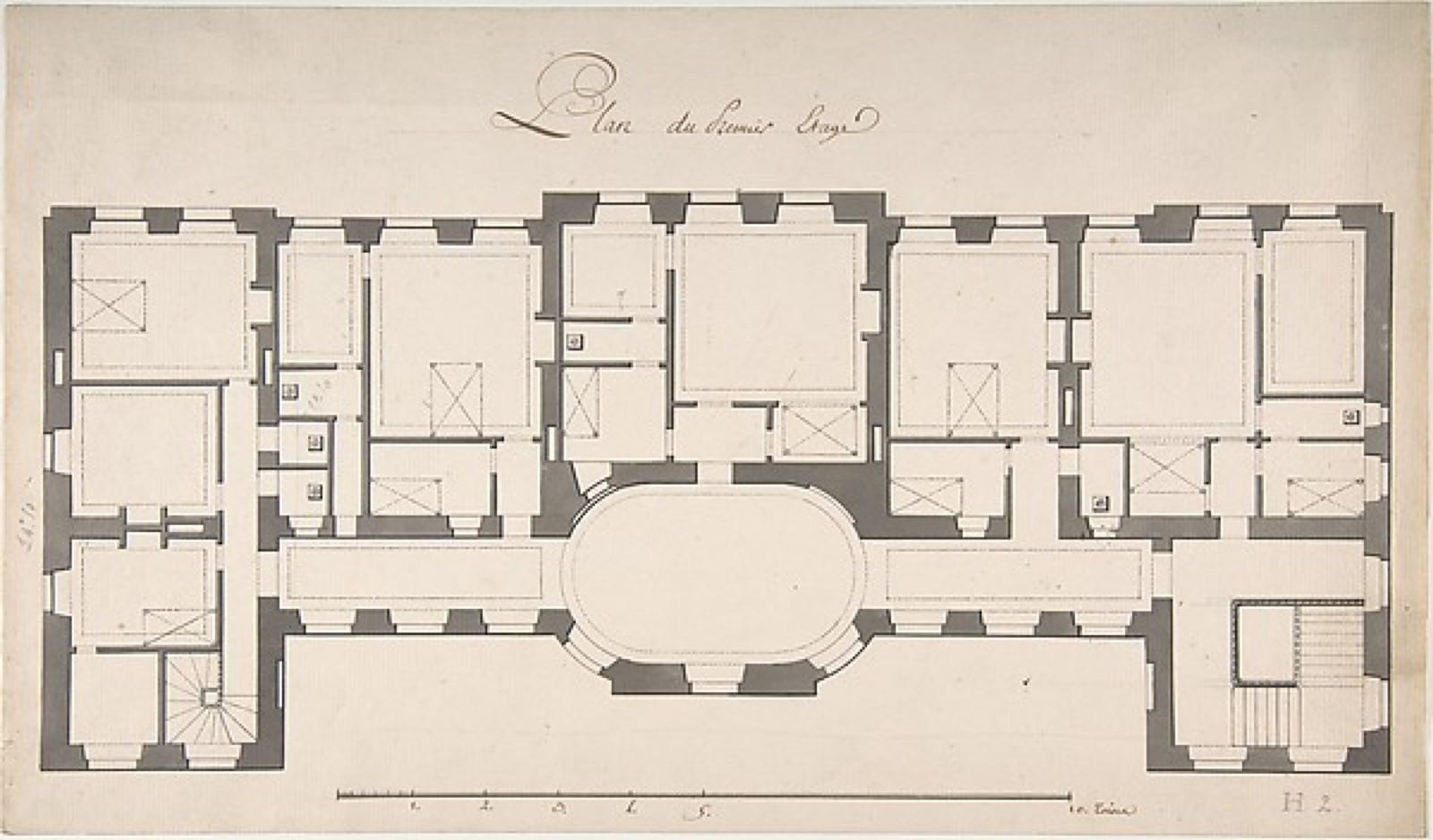
- Metropolitan Museum of Art, Degana/Raux ground plan for a palace.
- Metropolitan Museum of Art, Degana/Raux second-floor palace plan.
- Metropolitan Museum of Art, Karl Friedrich Schinkel, façade plan and elevation.
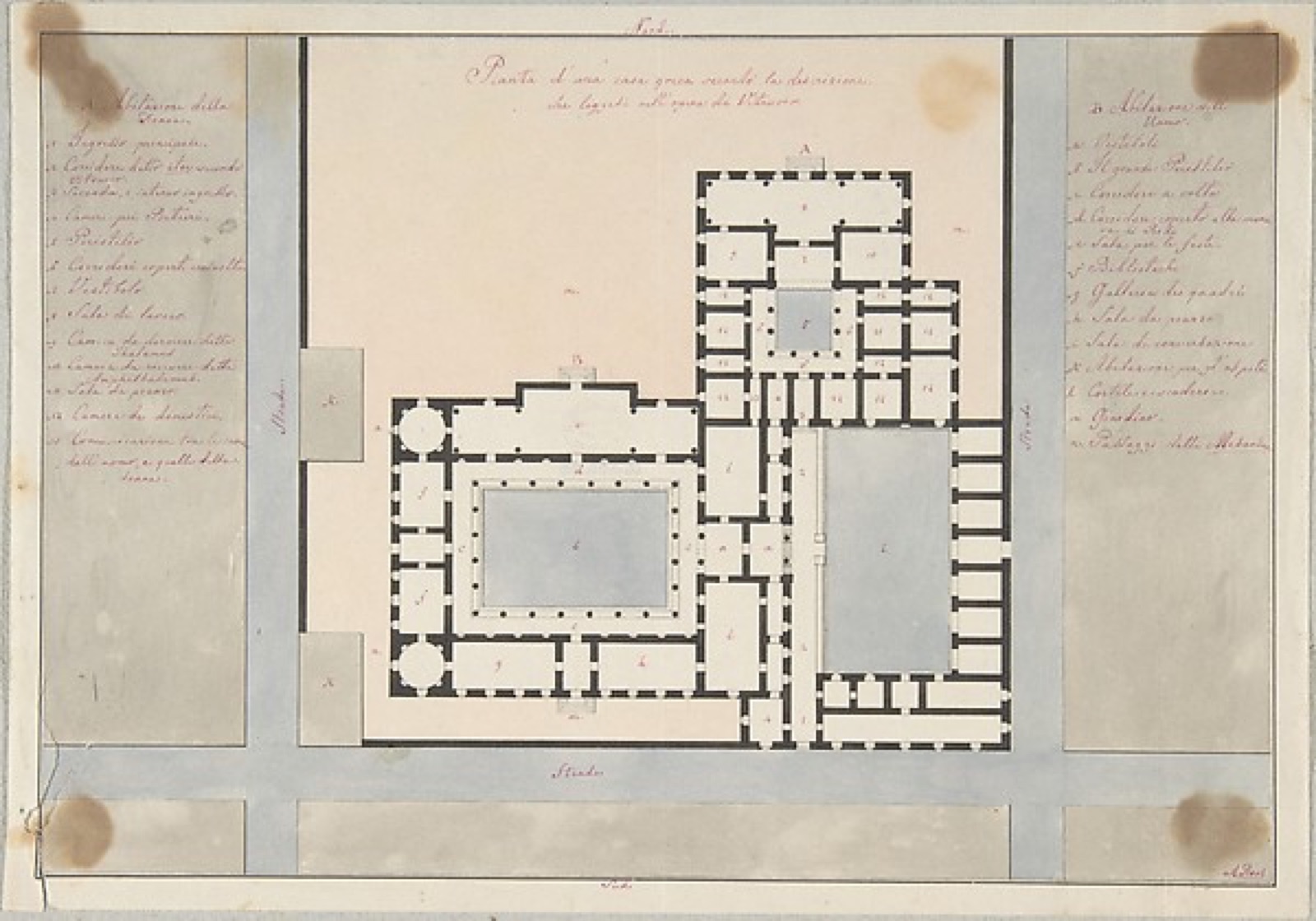
- Metropolitan Museum of Art, Anonymous Italian plan of a Greek house.
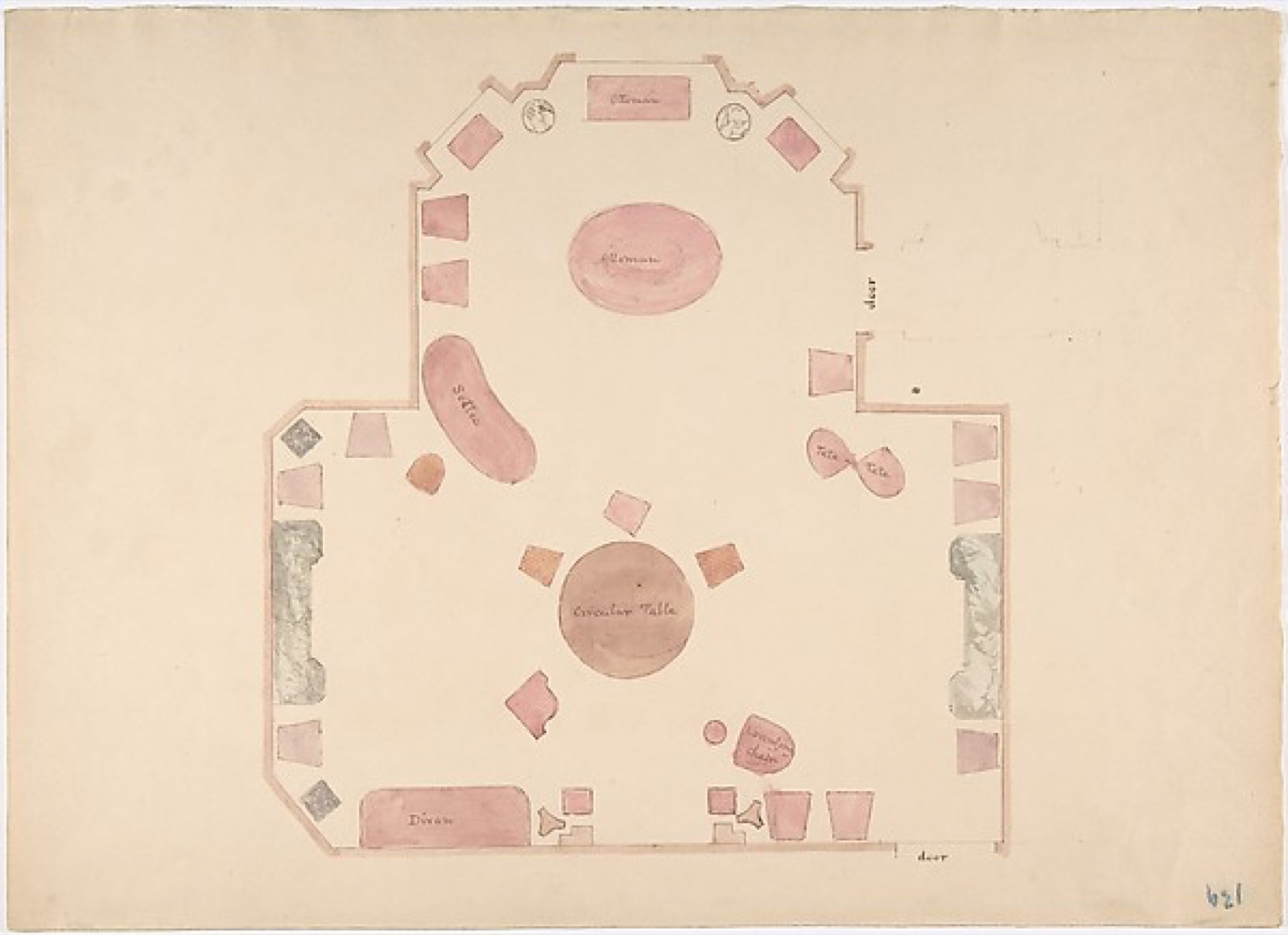
- Metropolitan Museum of Art, Anonymous British plan of a room.
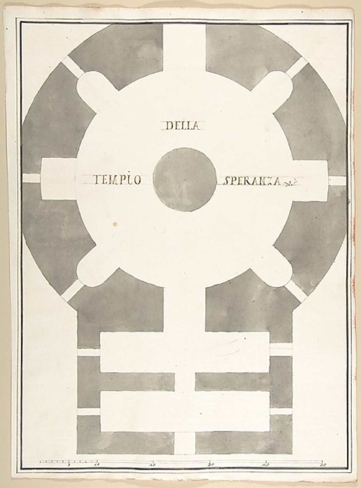
- Metropolitan Museum of Art, Pietro Paolo Coccetti, plan of Tempio della Speranza.
- Metropolitan Museum of Art, Anonymous French hotel-and-garden plan.
- Metropolitan Museum of Art, Workshop of Giuseppe Galli Bibiena, Dauphin catafalque ground plan.
- Metropolitan Museum of Art, Alexander Jackson Davis, Davenport house ground plan.
- Metropolitan Museum of Art, Anonymous French Palazzo dei Conservatori portico plan and other views.
- Metropolitan Museum of Art, Learning from Roriczer’s Pinnacle film.
- Metropolitan Museum of Art, Reconstructing a Gothic Vault Design film.
- Canadian Centre for Architecture, Plan as Perimeter catalogue/video.
Explore RELATED Architecture
These built-place pages show why plans, perspective, photographs and later records must be read together.
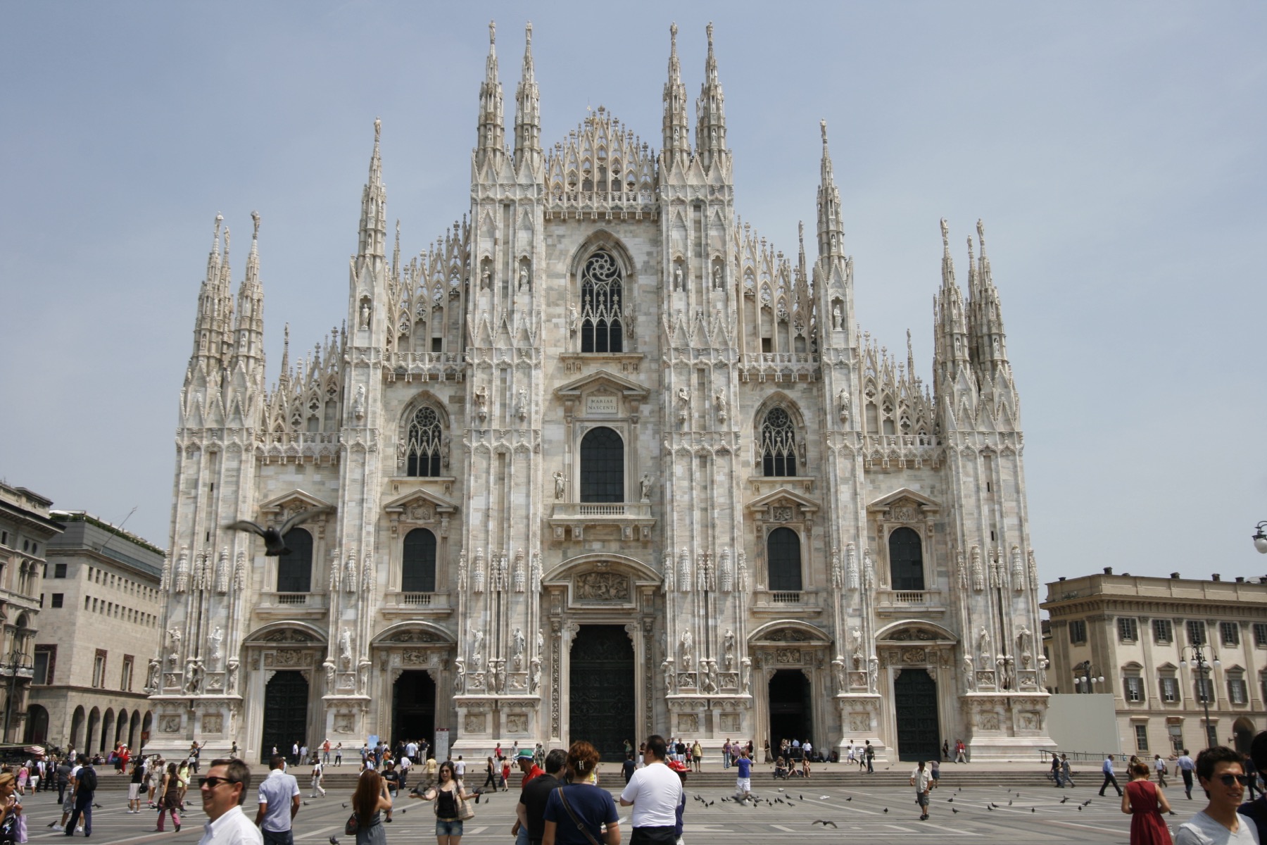
Milan Cathedral
Design and geometry changed through argument and building.
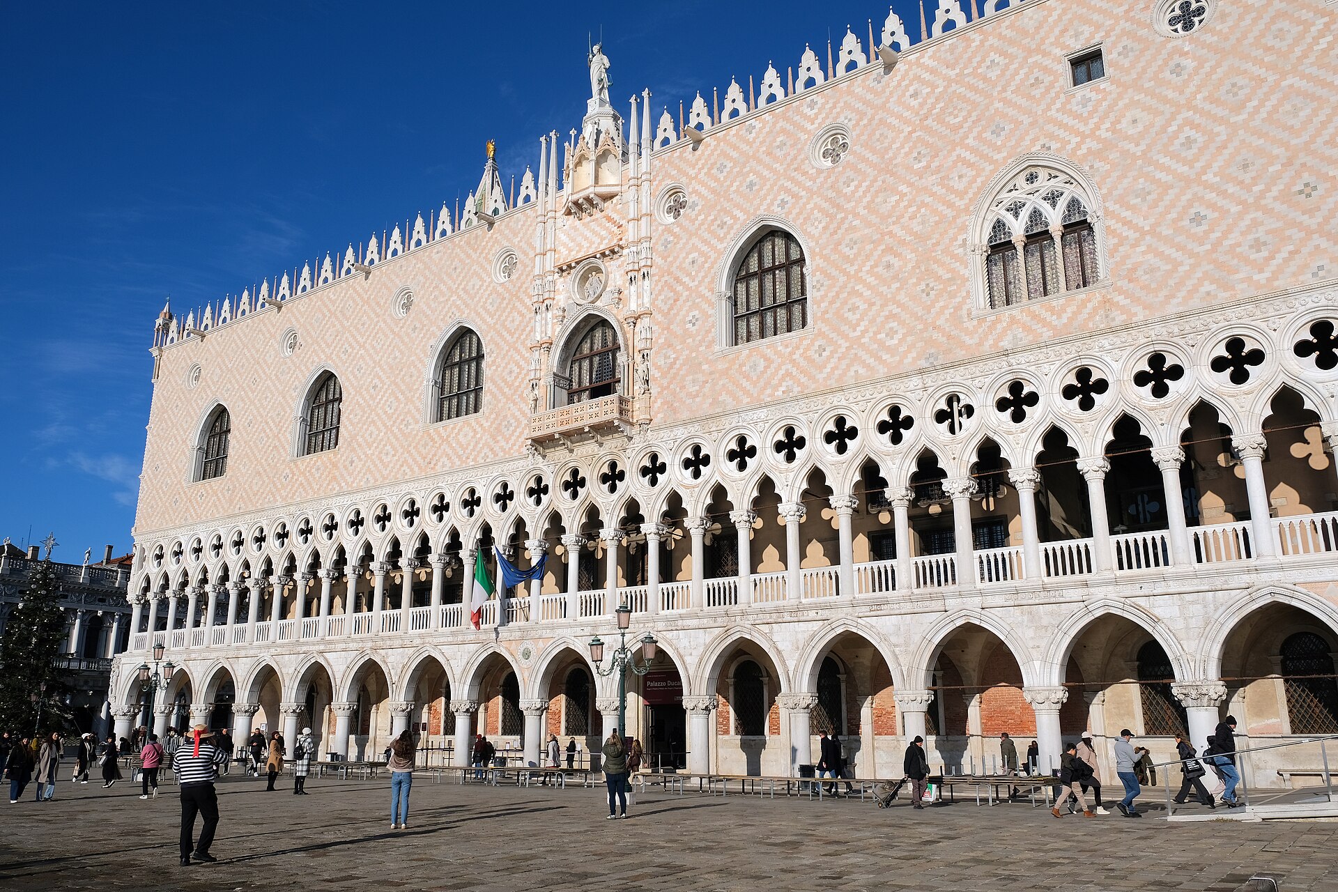
Doge's Palace
A facade conceals a long sequence of alterations and uses.
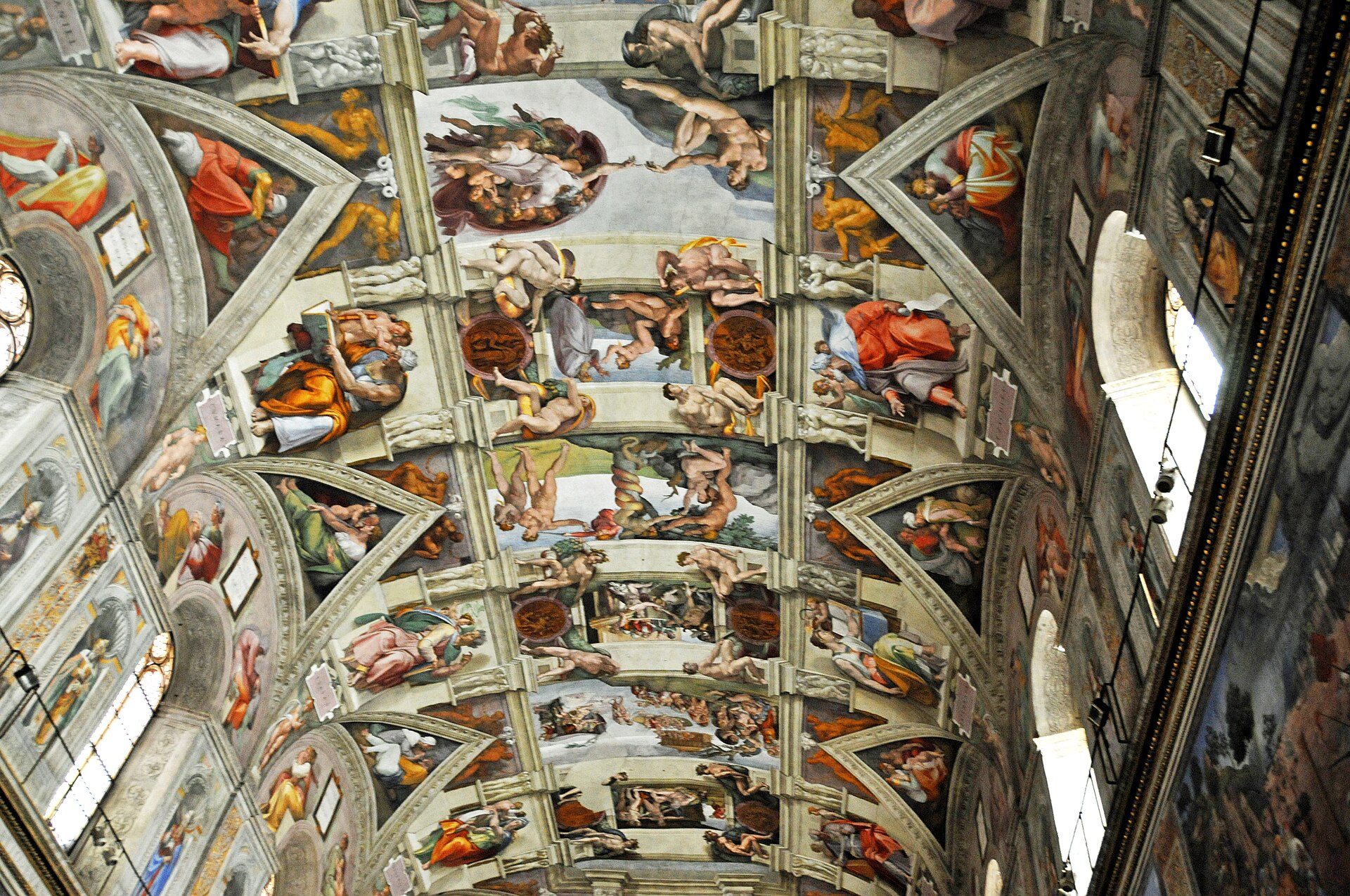
Sistine Chapel
Architectural fabric and painted programmes have different records.

Borobudur
Plan and visitor sequence reveal different spatial relations.

Machu Picchu
Ruins and later surveys mediate the reading of built terraces.
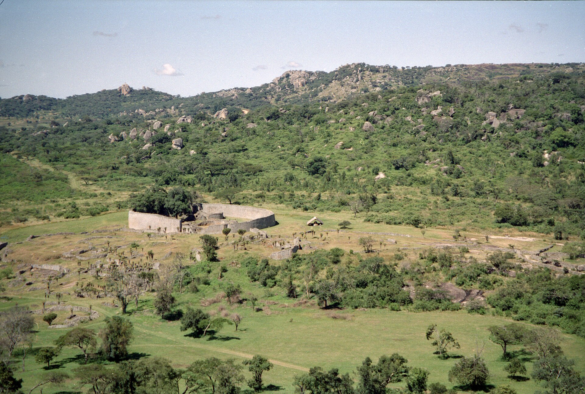
Great Zimbabwe
Heritage records must distinguish fabric from later inference.

Forbidden City
Palace plans and surviving courts changed across reigns.

Teotihuacan
Archaeological plan and exposed monuments are not the whole city.