


 by Tom Gurney
Tom Gurney BSc (Hons) is an art history expert with over 20 years experience
Email: tomgurney1@gmail.com / Phone: +44 7429 011000
Geometry, Building and Evidence
An isometric drawing presents width, depth and height together without making distant parts shrink or parallel building edges meet at vanishing points. That predictable geometry can clarify a stair rising through an office court, a roof frame above a barn, or changes to a house over half a century. Yet an isometric view is never the building itself. Its camera direction, cut surfaces and omissions decide which relations come forward. A useful isometric must therefore be read both as a measured visual system and as a choice about what deserves to be seen. [1], [5], [6], [7], [12], [20], [21], [22], [23]
The word also travels between disciplines with two meanings. In exact descriptive geometry, isometric projection is an orthographic parallel projection in which three main spatial axes are reduced equally. In everyday drawing practice, an isometric drawing often uses the same three-axis arrangement but sets true scaled lengths along the axes, so that the whole picture is somewhat larger than a strict projection. Digital architectural software sometimes calls any orthographic 3D view “isometric,” regardless of whether its three axes meet the exact equal-angle test. None of these usages means that every diagonal, curve or face is drawn at its natural size. Understanding what has been promised—and what has not—makes historic and contemporary examples far easier to interpret. [5], [6], [7], [8], [9], [10], [11], [12], [25]
At a Glance
- Basic viewThree principal spatial directions appear on one sheet, with parallel lines staying parallel rather than converging toward vanishing points. [5], [6], [7], [12]
- Exact projectionThe three projected axes meet at 120°, and their lengths share a reduction factor of about 0.816. [5], [6], [7], [8]
- Drawing conventionIn a full-axis isometric drawing, measured lengths may be laid out directly along the three axes; compared with a strict projection, the image is about 1.2247 times larger. [7], [8]
- What changes shapeHorizontal plans are slanted and foreshortened; circles on principal planes become ellipses; off-axis roof slopes and stairs need separately constructed points. [1], [7], [9], [12]
- Historic landmarkWilliam Farish described the method in a paper read in 1820 and printed in 1822, explicitly proposing buildings and cities as well as machines. [1], [2], [3], [4]
- Architectural usesExplain spatial circulation, record altered housing, compare building parts, disclose timber framing, or isolate a junction at detail scale. [14], [15], [16], [17], [20], [21], [22], [23]
- Critical limitAn isometric can reveal relations while concealing back faces, human occupation, exact unstated dimensions, materials' condition and construction tolerances. [7], [17], [20], [21], [22], [23]
- Best companionsDimensioned plans, sections and details, dated project or survey records, photographs, and the people whose use altered the building. [10], [17], [20], [21], [22], [23], [24], [25], [26]
Contents
- The equal-axis view: simple appearance, specific promise
- Farish's 1820 proposal and the 1822 printed paper
- Buildings as surveyed space: the Bradbury court
- Housing changes in a shared view: Aluminum City Terrace
- Frames and junctions: from barn to cornice
- Isometry in twentieth-century design and the problem of authorship
- Learning to draw the building rather than merely recognize it
- Digital models, camera choices and edited clarity
- How to read an isometric responsibly
The equal-axis view: simple appearance, specific promise
Imagine looking down toward one upper corner of a cube rather than straight at its front, side or top. A conventional upright isometric lays the two horizontal spatial directions at 30° above and below the paper's horizontal line, while the third direction stays vertical. Its three projected axes are separated by 120°. Opposite edges continue in parallel: a remote room bay does not diminish merely because it recedes on the sheet. A distant truss and the truss beside it can be compared within the same visual scale. Brown University's technical account distinguishes this equal treatment from dimetric and trimetric axonometric projections, whose principal directions receive unequal reductions. [5], [6]

Text alternative for the diagram
Three axes meet at 120 degrees; an invented building block keeps parallel edges parallel.
The familiar cube can be deceptively reassuring. In a mathematically exact orthographic isometric, no principal axis is displayed at its full three-dimensional length. Each has the same foreshortening factor, sqrt(2/3), or roughly 0.816. That shared factor allows many comparisons, but it is not the natural dimension of a real roof beam. A practitioner who draws full scaled lengths along the axes produces the related conventional isometric drawing, larger than the pure projection by 1/sqrt(2/3), approximately 1.2247. Autodesk's current AutoCAD support guidance describes precisely this difference for a standard isometric viewport. Its ratio applies to the standard equal-axis view: rotating the camera freely or measuring an inclined roof edge from the print does not preserve that shortcut. [5], [6], [7], [8]

Text alternative for the diagram
The same invented solid appears once at about 0.816-axis projection scale and once with full scaled lengths, a 1.2247 enlargement.
A rectangular ground plan drawn isometrically is not a rectangle of true shape on the page. It becomes a rhombus; orthogonal directions in the actual floor meet at 120° or 60° in the projection. A circle in a principal plane appears elliptical. A pitched roof line, diagonal brace, spiral stair or arch does not lie along one of the three measure-ready axes and cannot be taken directly from the same simple scale. Farish's original instructions already treat such elements through constructed points and ellipses. In a building drawing, the problem is not merely abstract: drawing a door opening or stair correctly requires knowing which points occupy which heights and planes. [1], [7], [9], [17]

Text alternative for the diagram
An invented plan square becomes a diamond, a circle becomes an ellipse, and a roof slope requires constructed endpoints.
The distinction from other architectural views matters. A perspective rendering lets an observer imagine standing somewhere, but it changes apparent size with depth. A plan gives the true horizontal arrangement and a section can cut vertically through the building, but neither reveals several differently oriented surfaces in a single angled picture. A plan-oblique or military drawing preserves the horizontal plan's shape while lifting it into a volume; an exact isometric instead treats the three axes equally and distorts the plan's outline. Catalan technical-drawing teaching at UPC names isometry, DIN-5, military and cavalier methods separately, and its architectural example removes, lifts or makes parts transparent to analyse hidden construction. The operation of cutting or lifting may look similar across them, but the projection's geometric promise is different. [6], [9], [10], [11]

Text alternative for the diagram
Four invented views contrast a flattened plan, converging perspective, preserved-plan oblique and equal-axis isometric.
Even an accurately constructed equal-axis image has a front and a back. A side wall, service zone or access route can be hidden behind the visible face. MIT's drawing teaching therefore expects a supplementary orthographic view where isometry conceals information required for making an object. For buildings, dimensioned plans, sections, elevations and local details remain necessary to identify levels, wall thickness, door clearances, connections and tolerances. This is not a failure of the isometric; it is the consequence of what one sheet can and cannot show. Spanish architectural-representation courses at UPC and German architecture teaching at Hochschule Campus Wien likewise teach multiple drawing modes rather than a single all-purpose projection. [7], [10], [19]
Farish's 1820 proposal and the 1822 printed paper
William Farish's On Isometrical Perspective was presented to the Cambridge Philosophical Society on 21 February and 6 March 1820 and appeared in the Society's transactions in 1822. The two dates are often flattened into a single “invention” year, yet they describe different events. Farish was addressing a practical communication difficulty. The lecture machines he used were assembled from standard components and then taken apart; explaining how to reassemble a particular apparatus to a distant helper was harder when its parts were split across separate plan, front and side views. Ordinary visual perspective could depict their appearance, but it introduced changing lengths that frustrated direct comparison. Equal treatment of three directions promised a picture that retained useful measured relations. [1], [2], [3], [4]
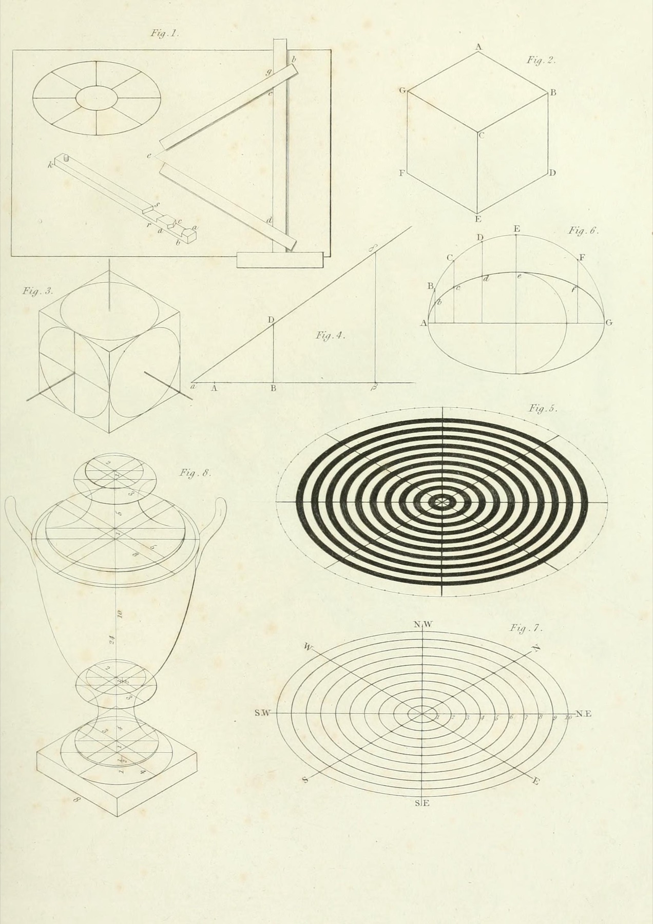
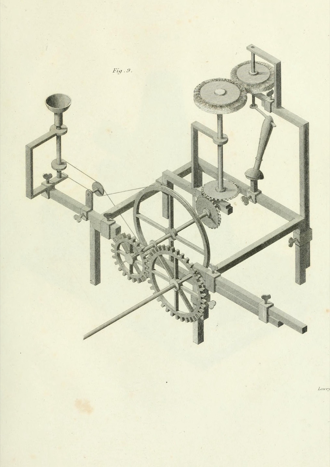
His first plate is an unusually clear statement of the idea's ambition. It links a straightedge arrangement to a cube, then shows circles becoming ellipses and constructs auxiliary scales. These are not ornaments around an effortless visual trick. The drawing table and ruler made equal-axis lines repeatable; templates and concentric elliptical guides helped represent wheel rims, pillars and curved elements. The details expose the labour beneath the apparently immediate three-dimensional image. His machine plate, engraved by Wilson Lowry, further shows how a network of vertical frames, shafts, gears and circular wheels can be made intelligible without vanishing points. Its point is the relation among parts, not an illusion that an eye could occupy the precise vantage implied by every surface. [1], [3]
The paper is especially relevant to architecture because Farish did not confine the method to machines. Printed pages 12–14 discuss bridges and circular or Gothic arches, columns and capitals, the courts and edifices of a cathedral, college or palace, their rooms and internal arrangements, and even the streets and monuments of a city. He suggested a distant architect or employer might mark what was wanted in an opened-up interior. A city view, he argued, could convey public buildings and houses together with their plan arrangement. These passages express proposed applications; they do not establish that nineteenth-century architectural offices adopted his technique on a large scale. Royal College of Art research on British architectural drawing observes that architects do not appear to have taken up axonometry immediately and asks whether model culture and other representational habits help explain the gap. That cautious finding is more defensible than either a story of instant diffusion or the claim that no architect ever tried it. [1], [4], [13]
Farish also identified the price of the method. Open many rooms or make too much hidden structure transparent and the drawing becomes a thicket of lines. A single cathedral interior could be manageable; an entire building full of rooms might not. He allowed a drafter to enlarge vertical dimensions, reveal what is hidden or choose a less exact appearance if the liberties were explained. That argument still applies to present-day exploded diagrams and amplified section models. A drawn tower made twice as tall for clarity may communicate information very effectively, but the reader must not mistake that vertical scale for the same equal-axis measure as the plan. [1]

Text alternative for the diagram
A clear opened building is compared with the same invented volume filled with overlapping room and level lines.
Farish's interest in an isometric city picture should not turn every earlier bird's-eye town or Chinese scroll into a strict isometric ancestor. Many historic artists used parallel-looking streets, raised buildings or mixed viewpoints without a calibrated 120° three-axis construction. Spanish/Galician research on the visual lineage of urban parallel depiction is useful here because it separates long image traditions from Farish's specific measured procedure. Curators may use “isometric” descriptively for historic elevated buildings, but the stronger geometric claim requires more than the appearance of parallel lines. [1], [13]
Buildings as surveyed space: the Bradbury court
The Bradbury Building's central court gives the isometric a spatial subject more difficult than a cube. Built in 1893 at Broadway in Los Angeles, the building surrounds a glazed internal volume with open stairs, elevator cages and iron-railed balconies. The Historic American Buildings Survey recorded it in 1968. Robert C. Giebner's sheet 7 is entitled Isometric of Central Court: it removes much of the enclosing office mass to show five floor levels, banks of stair flights, long galleries and the glazed roof together. The 1968 drawing is a survey interpretation of an existing building, not an original 1893 architect's proposal. [20]
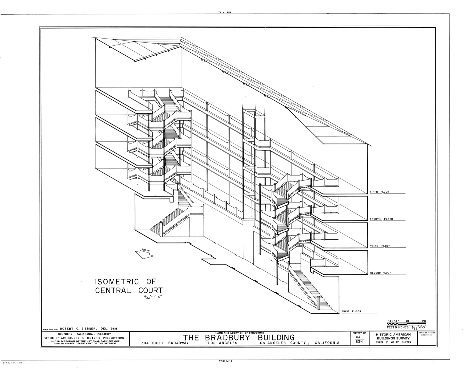
The court's length matters. In the typical-floor plan, two banks of rooms flank an elongated central opening; dimensions, door locations and fire-escape notes have a specificity the court isometric does not carry. Conversely, the plan flattens the galleries and stairs into one level. Giebner's isometric gathers the vertical paths and repeated balcony edges into a single volume, making the experience of crossing and ascending the interior intelligible as a relation. It cuts away enough outer wall to prevent the office façades from filling the view with irrelevant lines—an answer, in practice, to Farish's warning about crowded transparent interiors. The plan and isometric do different work, and neither replaces the other. [1], [20]

Text alternative for the diagram
Five invented court galleries and stairs repeat across a long central opening; the diagram does not trace the Bradbury survey.
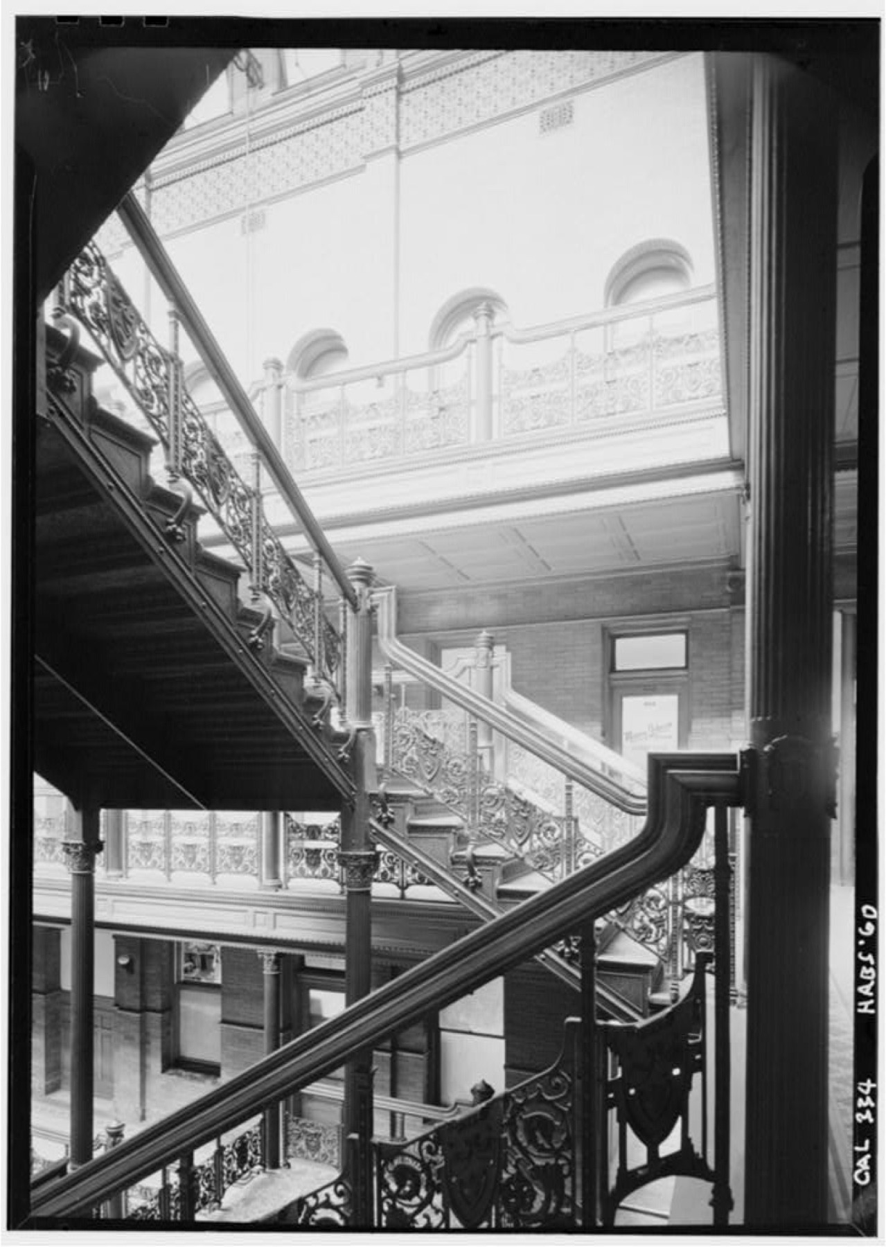
Jack E. Boucher's 1960 HABS photograph of the central court looking east restores a different knowledge. It shows ornamented iron stair flights, closely spaced rails and the actual surface and light of the court from an occupied walkway rather than from outside a transparent building. The photograph cannot give the same stable comparison of all five levels; the 1968 isometric cannot guarantee the photograph's light, texture or viewpoint. The court was also a workplace and circulation space for people occupying offices, not simply a beautiful gap between walls. To understand access, maintenance and contemporary use one would need additional dated observation; geometry alone does not settle those questions. [20]
Housing changes in a shared view: Aluminum City Terrace
At Aluminum City Terrace in New Kensington, Pennsylvania, Walter Gropius and Marcel Breuer designed federally sponsored defence-worker housing built in 1941–42. The later cooperative life of the project matters to its drawings. The Historic American Engineering Record's 1994 sheets do not present a frozen Modernist ideal; they compare the as-built homes with the homes the residents and cooperative inherited and altered. One sheet places two three-dimensional views side by side under the labels “Isometric—As Built” and “Isometric—Existing.” Their common orientation makes additions and substitutions visible as changes to the same housing form rather than as unrelated pictures. [21]
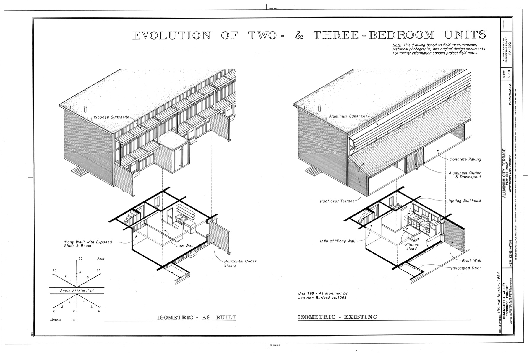
On the two-/three-bedroom sheet, the earlier view marks wooden sunshades, horizontal cedar siding and an exposed “pony wall” near a terrace. The later view records an aluminum sunshade and gutter/downspout, concrete paving, a roof over the terrace, a kitchen island and a relocated door. It also names Unit 198 and a modification by Lou Ann Burford around 1993. Those details are not incidental decoration. They make the isometric a record of how a dwelling was inhabited and adapted, while the separate annotations identify material and spatial decisions that a pure silhouette would miss. The comparison cannot by itself tell us Burford's reasons or the experience of every household in the cooperative; it does at least keep a named resident from disappearing behind the original architects' authorship. [21]

Text alternative for the diagram
Two invented houses share one isometric camera; a canopy, stair and terrace infill change in the later view.
A companion HAER sheet, Twin Houses, sets a floor plan and side elevation next to two isometric versions. The plan specifies bathroom, utility, kitchen, bedroom and living-room relations; the side elevation fixes the slope of the site and the height of the structural support. The earlier exploded isometric separates a cantilevered roof and cedar-clad body from steel columns on footings; the existing version shows changed enclosure, guttering, stair, infill and ground treatment. It is tempting to read the “as-built” label as an original 1940s drawing, but the cartouche credits Thomas Ingram, 1994, and says the sheet is based on field measurement, photographs and original design documents. It is a modern historical reconstruction compared with contemporary survey, not an untouched Gropius/Breuer print. [21]
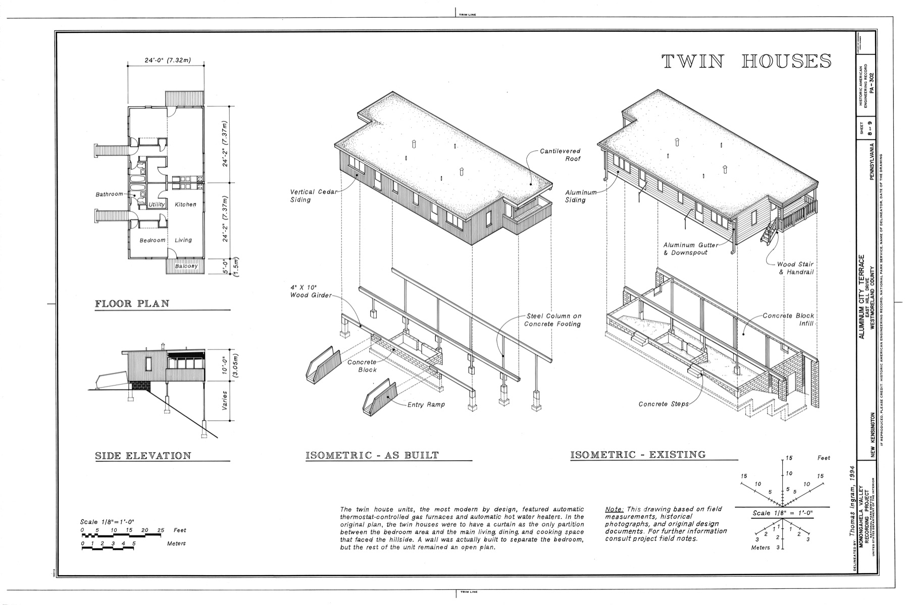
The shared camera angle is not a neutral guarantee of truth. A change on the hidden façade could evade both views, while a roof shown hovering above its supports may exaggerate separation to make structural order legible. The survey's noted sources and companion views are therefore indispensable. At the same time, the matched orientation allows a reader to ask a powerful architectural question: what happened to a dwelling after design, through maintenance, material replacement, personal modifications and cooperative decision-making? An isometric can make change visible without pretending that a building's life ended at its opening date. [1], [21]
Frames and junctions: from barn to cornice
An isometric can also remove surface without offering a before-and-after narrative. The Eli Whitney Armory barn at Hamden, Connecticut, is an early nineteenth-century timber structure. A 1974 Historic American Engineering Record sheet titled Isometric Projection shows its gabled roof partly stripped, with successive rafters, braces and framing bays visible through the body. The drawing is a later survey of a historic barn. It does not place us at an ordinary viewpoint in the barnyard: one portion retains cladding and roof surface while another exposes the skeletal members that construction and use would ordinarily hide. The adjacent smaller built volume supplies a site relationship, but the sheet's real subject is how an assemblage of members gives the large barn its form. [22]
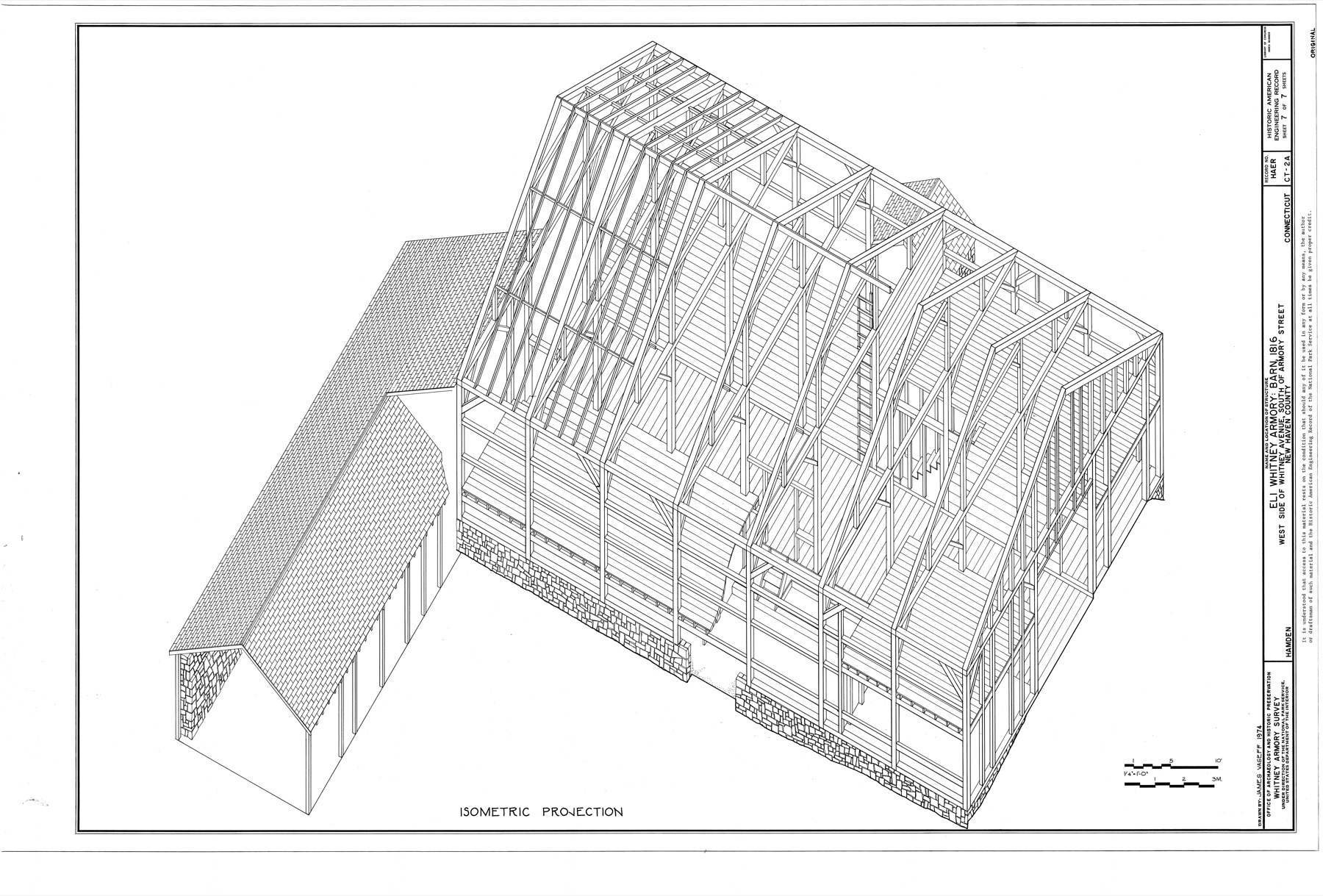
The line density demands care. A mass of parallel roof members may give a striking impression of structural repetition without telling a carpenter the size of a concealed joint or how individual timber was repaired. It can help locate the relation of bays, wall plates and rafters; section, detail and material records must still answer how connections work. The original barn served labour and storage within an armory complex. Reading it exclusively as a geometric marvel would erase that economic and human setting. [7], [22]
At the opposite scale, a Historic American Engineering Record sheet for the Structural Shop at Mare Island Naval Shipyard is named Isometric Cornice Section. It isolates the meeting of slate roofing, rafters, a gutter, roof truss members and a solid masonry wall, with annotations identifying sizes and material. Rather than using an isometric to describe a whole building, the delineator turns one roof-edge junction so that a carpenter's and mason's parts can be compared in one view. Its visual character is partly that of a section: material is cut and hatched, and the small view depends on text labels and dimensions. If detached from its survey and site, the sheet could be mistaken for a generic detail, yet it records one maintenance-intensive interface of a working naval shop. [23]
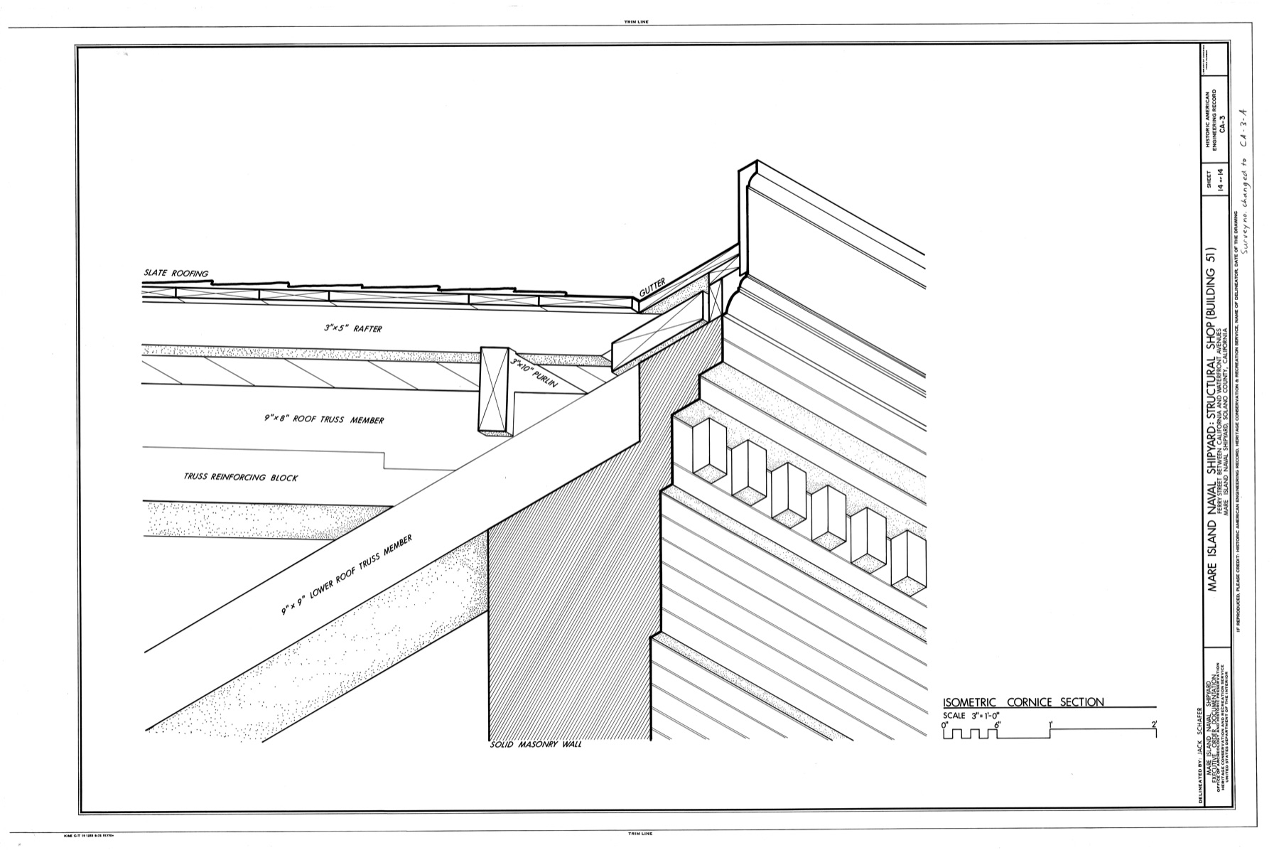
These two surveys demonstrate a useful change of scale. One exposes an entire repetitive frame; the other compresses attention to a point where roof, drainage and wall meet. Equal-axis geometry does not dictate either subject. The drafter decides the cut and the size of the pictured territory, then uses annotations to bridge from visible relation to specification. A full-frame isometric may be good for understanding the sequence of bays, while a local drawing remains necessary to know whether the gutter clears the wall or which member bears on which. [7], [22], [23]

Text alternative for the diagram
A whole invented roof frame is compared with an enlarged schematic gutter, rafter and wall junction.
Isometry in twentieth-century design and the problem of authorship
The survey examples must not obscure isometry's use in project design. In a Spanish study of constructive axonometry, Patricia Sabín-Díaz and Enrique M. Blanco-Lorenzo trace isometric depictions of James Stirling and James Gowan's 1957 Expandable House and their later Camberwell school work. The house was an unbuilt proposal associated with flexible growth, not an inhabited dwelling documented after alteration. Drawing Matter's archival discussion identifies James Gowan's hand in several preparatory sketches and notes that the competition work was undertaken within the Stirling/Gowan partnership. A Canadian Centre for Architecture project file likewise catalogues the partnership and separates models, plans, sections and written concept material. It would be inaccurate to treat all surviving study images as Stirling's personal drawings or to move their visual experiments to the house's “after construction” history. [14], [15]

Text alternative for the diagram
An invented small house volume branches into possible additions; these are design options, not an inhabited history.
Isometry gave the designers a way to picture one unit alongside potential added volumes without privileging a pedestrian eye point. However, an isometric of expandable masses does not tell us how easily a household could afford an addition, what local permissions were needed or how spaces would change in lived use. Those are matters beyond a design sheet. The Gowan sketches and partner records show the method as a way to test and argue for a proposition—distinct from an HAER survey asking how an already-built cooperative changed. [15], [21]
The Camberwell example makes drawing stage important. Recent Spanish/English scholarship on Stirling's model-making reports an early physical model and a final-project axonometric for the Brunswick Park School Assembly Hall. The latter was ink, coloured pencil and graphite on tracing paper. To label that presentation “the first sketch” because it shows a clear massing would invert the archive evidence. A designed school extension has to integrate roof form, openings, routes and material choices; a later isometric can communicate the resolved relation of these parts, while a working model may earlier have tested different spatial configurations. The drawing's medium and phase matter as much as its projection. [14], [16]

Text alternative for the diagram
An invented physical model, loose study drawing and final sheet have separate dates and jobs.
The Metropolitan Museum of Art catalogues Tadao Ando's 1980 Nakanoshima Project, Osaka City Hall, isometric view. Its medium—lithographic crayon over half-tone lithographs—reminds us that an isometric architectural sheet can be an authored art object, with texture and compositional force, as well as an explanation of mass. The museum record establishes the sheet's title, maker and medium; it does not by itself verify a constructed city hall. Nor should the drawn project be confused with a photograph of built work. [24]
Learning to draw the building rather than merely recognize it
The apparently simple isometric can be difficult to produce reliably. Naomi Ando's Japanese-language account of an architecture drawing course at Hosei University began with students constructing a small physical building model, then making isometric drawings and later working with plans and sections. The model helped students grasp that doors and windows belong to particular surfaces. Nevertheless, the drawn openings were sometimes omitted or placed inaccurately even when students could imagine the box-like house. In one fifty-student exercise, only two drawings were rated fully accurate and carefully completed; twenty-three were incomplete or erroneous. That is a bounded classroom observation from 2007, not a population-wide failure rate for architecture students. Its durable lesson is that recognizing a three-dimensional form is different from understanding how specific lines, cuts and openings must be projected. [17]

Text alternative for the diagram
A correctly located invented door is compared with an opening accidentally lifted into the roof face.
Ando found the same tension in section drawings. A student might see a building as a volume but still confuse the line that marks a cut surface with an edge seen beyond it. Plan and section require their own graphic conventions; a model can help compare physical structure with representation, but it cannot excuse sloppy line hierarchy. Her conclusion therefore differs from an easy claim that an isometric “makes everything clear.” It makes some whole-object relations easier to imagine, while exact drafting remains a learned practice requiring cross-checks. [17]
In Japan, a separate 2018 design-research abstract describes researchers and designers exchanging isometric illustrations to clarify complex scientific work. Its setting is not building documentation, so it should not be used as proof of an architectural outcome. It does, however, underscore a general value also visible in Farish's machine context: a shared three-axis picture can be a medium for discussion among people with different forms of expertise, and iterative correction is part of making it trustworthy. [1], [18]
Digital models, camera choices and edited clarity
Digital practice makes a building's orthographic 3D view quicker to generate. Autodesk's 2026 Revit guidance explains that a common building model can produce plans, elevations, sections, orthographic 3D and perspective views, with a model change propagated across the views. That link is useful for coordination, but the presence of an “isometric” menu item is not proof that a custom camera orientation follows the 120° equal-axis setup. Even a correctly angled projection can preserve parallel geometry while displaying omitted elements, inaccurate model contents, unverified material junctions or an obsolete project phase. A model-derived image still needs a date, view description and checked information. [8], [25]

Text alternative for the diagram
One invented model yields a whole orthographic view, cut view and perspective camera; the model alone does not verify information.
Architect Steven C. Shell's Autodesk University account of an existing building and proposed mezzanine shows why the view is sometimes assembled rather than simply exported. He describes duplicating and aligning orthographic/isometric views, changing phases, making parts transparent and halftoning the base so that the new structure can be read against what remains. Those operations could clarify a renovation without pretending that transparency is a physical property of the wall. They also require honest captions: a ghosted existing shell, highlighted new mezzanine and removed component are different statuses, not simultaneous visible surfaces of a finished building. [26]
The ease of orbiting a model may also encourage a tempting terminological blur. Autodesk's own Revit documentation uses “isometric” alongside “orthographic” to distinguish a non-perspective 3D view from a camera perspective. In exact projection theory, orthographic does not automatically mean equal-axis isometric; a freely rotated orthographic view could be dimetric or trimetric. Architectural readers can accept a software menu's looser word while identifying whether a published drawing is a calibrated equal-axis construction, a general parallel 3D view or a deliberately exploded analytical composition. [5], [8], [25]
How to read an isometric responsibly
Start with the drawing's status. Farish's machine plate accompanied a printed method; Gowan/Stirling's house studies belong to an unbuilt design experiment; Giebner's Bradbury isometric surveys a standing 1893 office court in 1968; Ingram's Aluminum City Terrace sheet reconstructs a wartime as-built state in 1994 and compares it with a modified cooperative home; the Whitney barn and Mare Island cornice are later measured records. The same parallel geometry does not make these sheets equivalent evidence. A title, cartouche, maker, year and source note should be read before the shape is used to make a historical claim. [1], [15], [16], [20], [21], [22], [23], [24]

Text alternative for the diagram
Invented sheets labelled proposed design, reconstructed as-built state and later measured survey have different evidence status.
Next ask what has been cut, lifted or concealed. The Bradbury court becomes legible because the offices are removed; the Whitney barn's surface is partly absent so that roof members appear; Aluminum City Terrace's roofs hover above supports to show change; the Mare Island detail exposes a cornice interior. Transparency and exploded separation are explanatory devices, not visible facts. Conversely, a rear wall or hidden path may remain absent from view even if the drawing looks complete. Multiple views and a photograph should be consulted where the invisible part carries the question being asked. [1], [9], [20], [21], [22], [23]
Then read the scale and measures. Equal axis ratios do not make every sloping line measurable. The paper may use the conventional undiminished-axis drawing scale rather than the strict foreshortened projection; it may amplify height or separate layers; a photographed or scanned image may have been resized for a page. Figures printed with dimension lines and source scales should be respected, and unstated dimensions should not be inferred from browser pixels. A knowledgeable reader can reconstruct a dimension with the known projection and coordinates, but an article image is not a substitute for a specification. [1], [7], [8], [20], [21], [22], [23]
Finally ask whose architectural life the sheet includes. Farish's tools addressed work between lecturer and assistant; the Bradbury drawing reveals office circulation but not the daily experience of its occupants; the Aluminum City Terrace record names Lou Ann Burford and signals residents' alterations; the Whitney barn and Mare Island shop were workplaces. An isometric helps us see physical relationships without proving social relations or erasing the people who maintained and changed buildings. It earns its place in architectural history when its very clarity is set alongside the records, photographs and voices it cannot contain. [1], [20], [21], [22], [23]

Text alternative for the diagram
A visible volume relation is paired with plan dimensions, section, photo and dated record that can test what the isometric omits.
Related Drawings and Reading
Farish's printed plates, Ando's museum-held 1980 project drawing and archival sheets for Stirling/Gowan can be read as authored graphic objects with distinct purposes. Their artistic presence should not override whether they are a technical demonstration, an unbuilt proposal, a presentation sheet or a later survey. [1], [15], [16], [24]
Northwestern University's graphics-sketching tutorials demonstrate isometric hand construction alongside orthographic, oblique and perspective methods, while Ray Lucas's Drawing Parallels offers extended architectural discussion of axonometric, isometric and oblique drawing. Edward Robbins's Why Architects Draw is a broader reading on how drawings direct ideas, production and professional communication. [27], [28], [29]
Explore RELATED Artworks and Records

Farish geometrical plate
The equal-axis procedure as a technical printed object
William FarishBradbury court survey
A later measured drawing of circulation
Robert C. Giebner for HABSAluminum City Terrace comparison
A dated record of altered housing
Thomas Ingram for HAERMare Island cornice
A local construction junction
Historic American Engineering RecordWatch: Isometric Sketching at Northwestern University
The Segal Design Institute lists isometric hand-sketching tutorials alongside orthographic, oblique and perspective instruction. [27]
Constructing the equal-axis view
Compare the institute’s straight-edge and freehand isometric modules with this article’s distinctions between convention and pure projection.
Original schematic preview, not a video still.Frequently Asked Questions
No. Strict isometric is an equal-axis member of the orthographic axonometric family; plan-oblique and elevation-oblique drawings preserve different faces and should not be silently relabelled. [5] [6] [7]
Pure orthographic isometric projection foreshortens all three principal axes equally to about 0.816. A full-axis drawing uses the same geometry but lays measured axis lengths at 1.0, giving a view about 1.2247 times larger. [7] [8]
No. He published a specific equal-axis procedure in 1822. Earlier lifted or parallel-looking images exist, but they should not be called exact isometrics without evidence of their geometry. [1] [3] [13]
No. Robert C. Giebner drew the court isometric for HABS in 1968, long after the 1893 Bradbury design; Jack E. Boucher’s companion photograph dates to 1960. [20]
The 1994 Thomas Ingram HAER sheets are later as-built and existing-condition survey records. They compare reconstructed original conditions with residents’ later alterations, including a named unit. [21]
References
- William Farish, On Isometrical Perspective, Transactions of the Cambridge Philosophical Society 1 (1822), original facsimile.
- Cambridge Philosophical Society, foundation and early years.
- Frances Robertson, University of Glasgow MPhil dissertation on mechanical illustration (2003).
- Rachel Wells, Royal College of Art PhD dissertation on architectural representation (2019).
- Brown University, Axonometric Projections.
- University of Oregon, architectural projection and drawing.
- MIT OpenCourseWare, Drawing and Sketching.
- Autodesk Support, Isometric viewport not in true scale.
- UPC ETSAV, Catalan axonometric architectural analysis exercise.
- UPC ETSAB, Spanish Architectural Representation II syllabus.
- Columbia GSAPP, Introduction to Projection.
- Library of Congress Graphic Materials thesaurus, Axonometric projections.
- University of Granada, parallel urban imagery research record.
- Patricia Sabín-Díaz and Enrique M. Blanco-Lorenzo, La axonometría constructiva en arquitectura, UPC 2018 proceedings.
- Canadian Centre for Architecture, Stirling/Gowan Expandable House file; Drawing Matter, James Gowan's sketches.
- Isaac Mendoza and Fernando Linares, James Stirling: tradition and evolution of the artisan model maker, VLC arquitectura 11:2 (2024).
- Naomi Ando, Japanese paper on cut, projected and solid drawings as architectural drawings, Japanese Society of Graphic Science (2007).
- Ikuyo Ueda and colleagues, Japanese abstract on isometric collaborative visualisation, Japanese Society for the Science of Design (2018).
- Hochschule Campus Wien, Architektur—Green Building programme.
- Library of Congress HABS, Bradbury Building, including 1968 court isometric sheet 7, typical-floor plan sheet 3 and Jack E. Boucher's 1960 central-court photograph 3.
- Library of Congress HAER, Aluminum City Terrace, including 1994 two-/three-bedroom sheet 6 and twin-houses sheet 8.
- Library of Congress HAER, Eli Whitney Armory Barn, 1974 isometric projection sheet 7.
- Library of Congress HAER, Mare Island Naval Shipyard Structural Shop, isometric cornice section sheet 14.
- Metropolitan Museum of Art, Tadao Ando Nakanoshima Project, Osaka City Hall, isometric view (1980).
- Autodesk Revit LT, View the Model.
- Steven C. Shell, Autodesk University, Revit architectural presentation with multiple aligned isometric views (2018).
- Northwestern University Segal Design Institute, Graphics Instruction & Sketching video tutorials, including isometric construction modules.
- Ray Lucas, Drawing Parallels: Knowledge Production in Axonometric, Isometric and Oblique Drawings, Routledge.
- Edward Robbins, Why Architects Draw, MIT Press.
Explore RELATED Architecture
The larger axonometric family, plans, sections, elevations, architectural models and measured surveys each make different information visible. A companion page on axonometric drawings explains broad architectural naming and plan-oblique alternatives; the present page concentrates on equal-axis construction and isometric architectural practice. [5], [6], [7], [8], [9], [10], [11], [12]
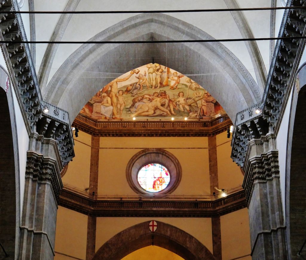
Florence Cathedral
The dome’s supports call for a structural cut and measured companions to any lifted view.
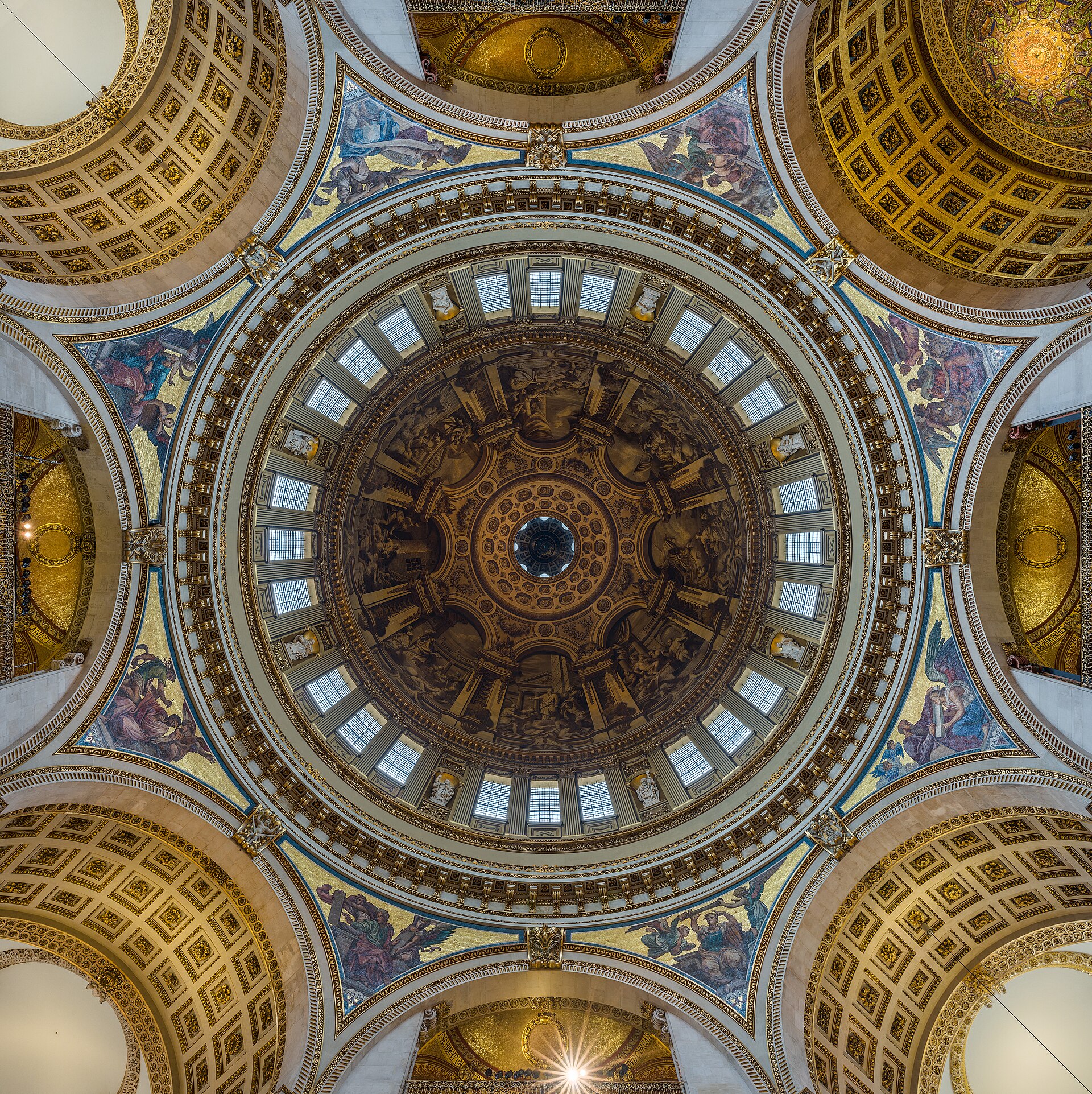
St Paul’s Cathedral
An isometric roof cut can separate overhead layers that an interior photograph merges.
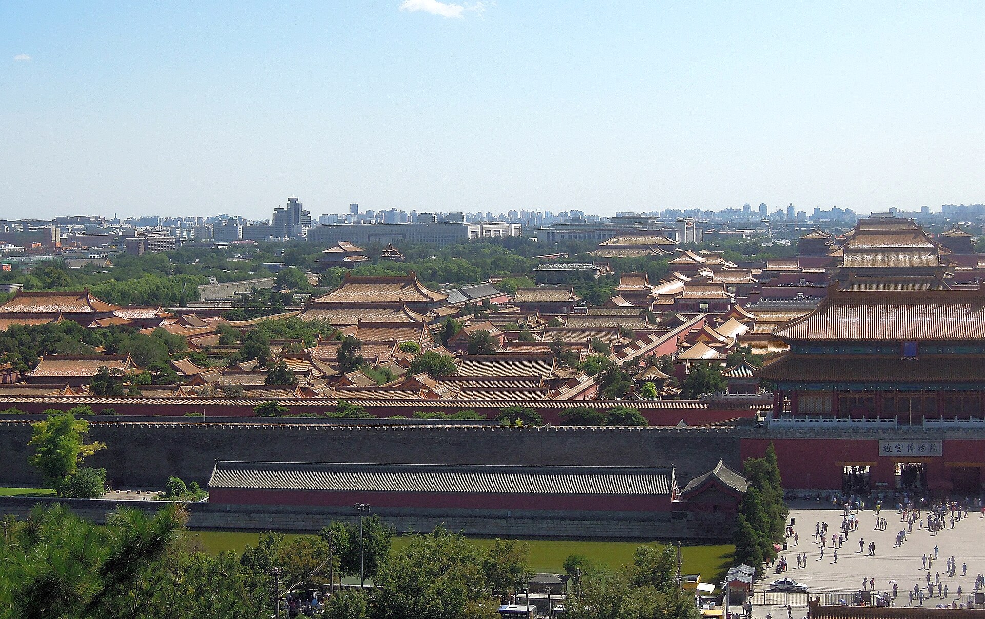
Forbidden City
Repeated courts and galleries test how a long built sequence fits a single parallel view.

Machu Picchu
Terraces and routes expose the need for topographic and sectional evidence beside a lifted sketch.
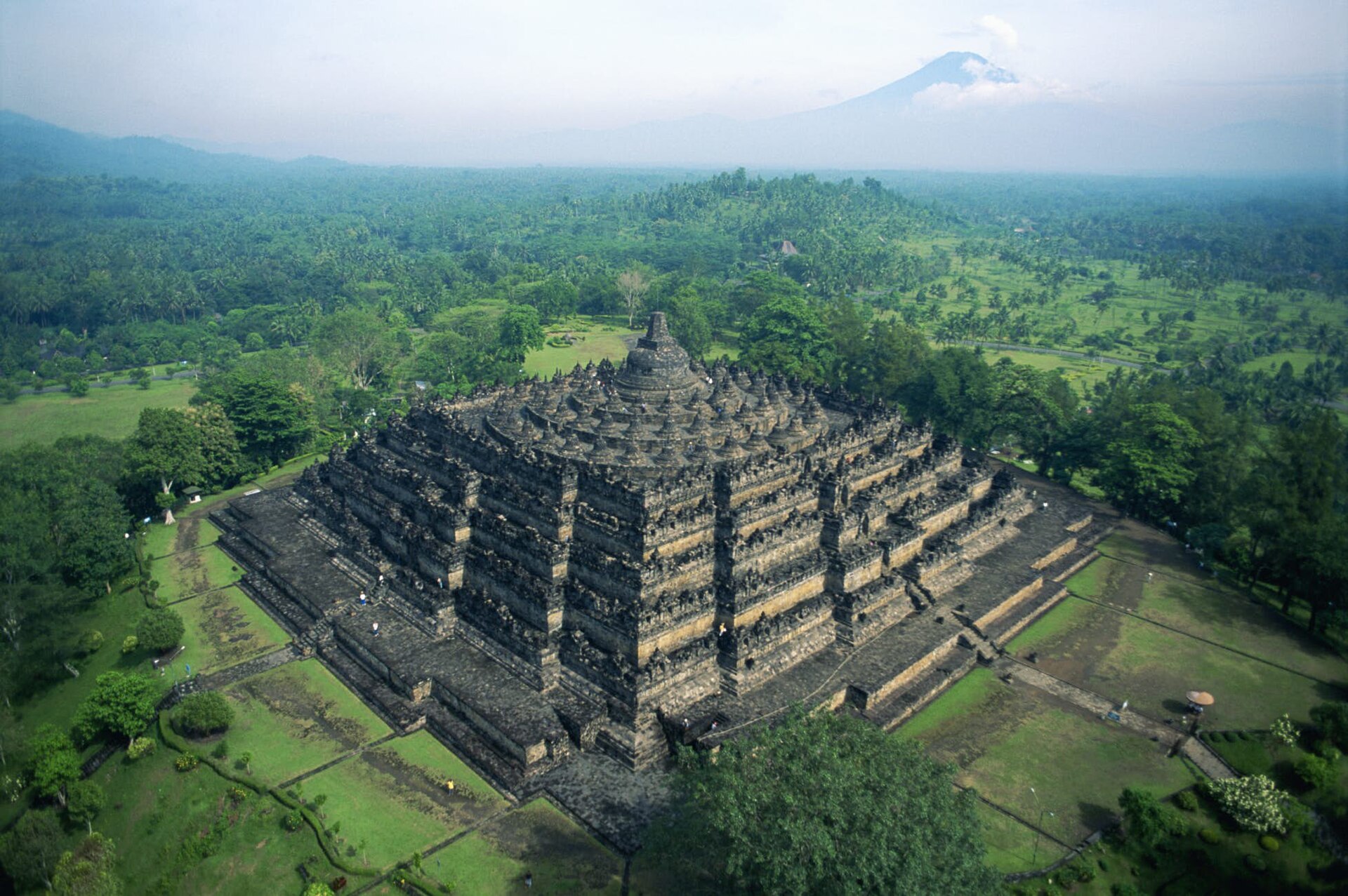
Borobudur
Successive levels invite a spatial projection but still require precise plan and visitor-route evidence.
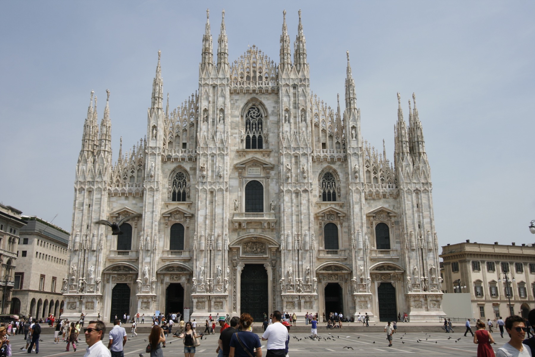
Milan Cathedral
Bays and roof framing become legible when an entire envelope is selectively opened.
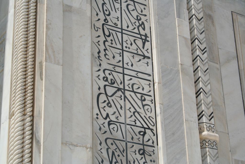
Taj Mahal
The garden axes can be tested against a dimensioned plan rather than inferred from a diagonal view.
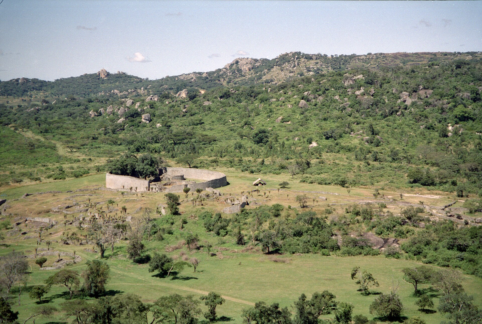
Great Zimbabwe
Separate enclosures reveal why a site projection must distinguish built phases and incomplete evidence.